
A backup power supply charge and discharge control circuit for a remote communication base station

A charging and discharging control and backup power technology, applied in the field of communication, can solve the problems of low stability and reliability, complicated charging and discharging control circuit of the backup power supply of the remote communication base station, etc.

Active Publication Date: 2015-11-25
浙江南峰电气有限公司
View PDF6 Cites 0 Cited by
  • Summary
  • Abstract
  • Description
  • Claims
  • Application Information

AI Technical Summary

Problems solved by technology

[0005] The technical problem to be solved by the present invention is that the remote communication base station backup power supply charging and discharging control circuit is complicated in the prior art, and the stability and reliability are not high, so as to provide a remote communication device with simple design and high stability and reliability. Communication base station backup power supply charge and discharge control circuit

Method used


Image

  • A backup power supply charge and discharge control circuit for a remote communication base station
  • A backup power supply charge and discharge control circuit for a remote communication base station
  • A backup power supply charge and discharge control circuit for a remote communication base station

Examples


Embodiment 1

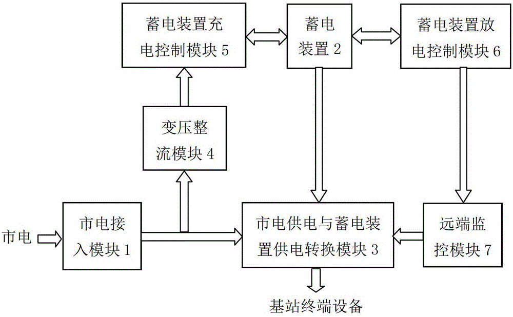
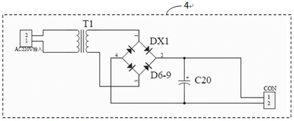
[0055] This embodiment provides a remote communication base station backup power supply charge and discharge control circuit, its structural block diagram is as follows figure 1 As shown, in this embodiment, the remote communication base station backup power supply charge and discharge control circuit includes a mains power access module 1, a power storage device 2, a mains power supply and power storage device power conversion module 3, and a transformer rectification module 4 , the charging control module 5 of the electric storage device and the discharging control module 6 of the electric storage device.

[0056] The mains power access module 1 is used for mains power connection and includes an output terminal for externally outputting alternating current.

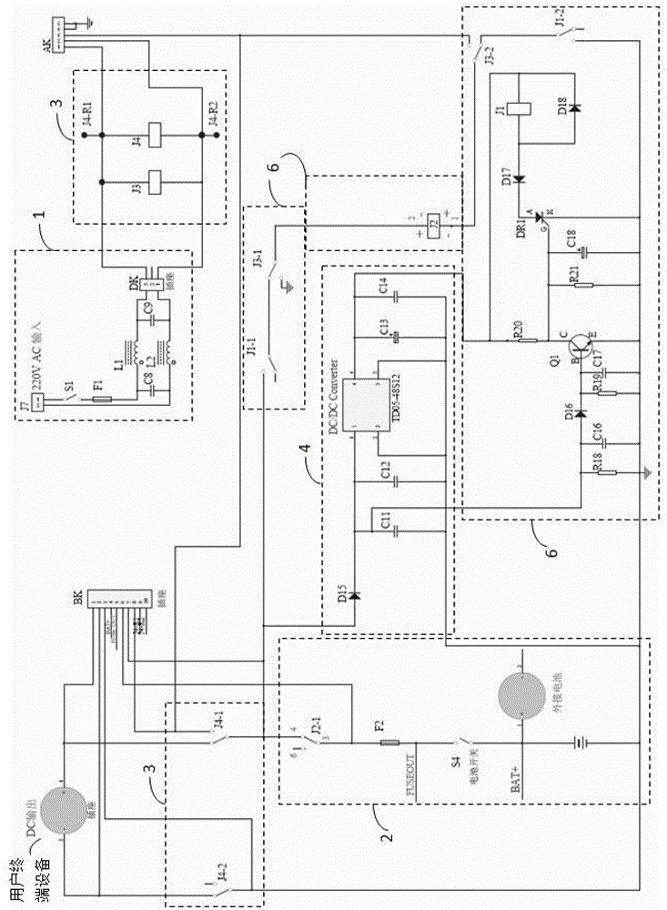
[0057] Such as figure 2As shown, the mains access module 1 includes a switch S1, an insurance component F1, common mode inductors L1, L2, capacitors C8, C9; one end of the switch S1 is connected to the positive pole o...

Embodiment 2

[0091] In this embodiment, on the basis of the above embodiments, the discharge control module 6 of the electric storage device further includes a debugging unit 8 for debugging the magnitude of the current passing through the undervoltage detection control unit. Such as Figure 5 As shown, the debugging unit 8 includes resistors R16, R17, and a capacitor C15. One end of the resistor R16 is used as the input terminal of the debugging unit 8 and connected to the output terminal of the DC / DC transformer unit. The resistor R16 The other end of the resistor R17 is connected to one end of the resistor R17, one end of the capacitor C15, and the other end of the capacitor C15 is grounded; the other end of the resistor R17 is used as the output terminal of the debugging unit 8 to connect to the undervoltage detection input to the control unit. By replacing the resistor R16 to limit the size of the base current passing through the triode Q2, the preset lower limit voltage of the stora...

Embodiment 3

[0094] In this embodiment, on the basis of the above-mentioned embodiments, the remote communication base station backup power supply charge and discharge control circuit also includes a remote monitoring module 7 for remote monitoring of its working status, and the remote monitoring module 7 is a dynamic Ring monitoring system interface FK; the mains power supply and power storage device power supply conversion module 3 also includes a first signal sending unit for sending the mains power supply and power storage device 2 working status signals to the remote monitoring module 7, so The first signal sending unit is the changeover contacts 3 and 4 of the relay J1, and the electric storage device discharge control module 6 also includes a second signal sending unit for sending to the remote monitoring module 7 whether the electric storage device 2 is undervoltage. unit, the second signal sending unit is the changeover contact 4 of the relay J3.

[0095] Such as Figure 6 As sho...


PUM


Abstract

The invention relates to a standby power supply charge-discharge control circuit for a far-end communication base station, which comprises a mains supply access module, an electrical storage device, a mains-supply power supply and electrical storage device power supply conversion module, an electrical storage device charging control module, an electrical storage device discharging control module and a far-end monitoring module. When a mains supply supplies power to base station equipment, a standby power supply charging control module controls the electrical storage device to be in a charging state; and when the mains supply has a fault, the mains-supply power supply and electrical storage device power supply conversion module controls the electrical storage device to supply power to the base station equipment so as to enable the base station equipment to normally work and enable software and hardware of the base station equipment not to be damaged, and simultaneously, the operating state of the standby power supply charge-discharge control circuit of the far-end communication base station can be monitored at a control center by the far-end monitoring module. The invention provides the standby power supply charge-discharge control circuit which is directly supplied with power by adopting the electrical storage device, has under-voltage protection and electrical storage device protection, has a simple circuit structure, is low in cost, is developed by a modern electrical and electronic device and has relatively high stability and reliability.

Description

technical field [0001] The invention relates to a backup power supply device of an intelligent remote communication base station, belonging to the technical field of communication. Background technique [0002] With the development and improvement of communication technology, equipment such as wireless local telephone base stations, micro-cell base stations of mobile marginal networks, CDMA micro-base stations, and repeaters have been used on a large scale. These base station equipment are generally installed outdoors exposed to the sun and rain, and installed on the roof of a building or on a utility pole or on a mountain top where the power supply quality is particularly poor. [0003] There are generally two power supply methods for base stations: one is 48VDC DC remote feed, which is suitable for small base stations with low power consumption; the other is 220VAC mains AC local power supply for base stations with large power consumption. For base station equipment with ...

Claims


Application Information

Patent Timeline
Patent Type & Authority Patents(China)
IPC IPC(8): H02J9/06H02J7/02H02H7/18
Inventor 周庆南
Owner 浙江南峰电气有限公司
Learn More