
Preparation method for optical thin-film of polaroid

An optical film and polarizer technology, applied in the optical field, can solve the problems of easy dust accumulation, high material consumption, and low service life, and achieve the effects of reducing fatigue, good wear resistance, and good heat resistance

Inactive Publication Date: 2015-04-15
上海图锐数码科技有限公司
View PDF4 Cites 0 Cited by
  • Summary
  • Abstract
  • Description
  • Claims
  • Application Information

AI Technical Summary

Problems solved by technology

However, the polarizer used in the polarized stereoscopic imaging in the prior art is made of plastic material, and is dyed with a copper sulfate solution to form a polarizer. Its defects are: low light efficiency, easy to accumulate dust, easy to scratch, It consumes a lot of materials and the process is complex; thus directly causing the following disadvantages in the existing polarization stereoscopic imaging effect: a. Low imaging light efficiency, due to the characteristics of plastic materials, the overall light efficiency is relatively low; b. Imaging is uneven, The images seen by the left and right eyes have inconsistent clarity in different parts; c. There are double images in the imaging, the image contrast of the left and right eyes is poor, and the crosstalk is high; d. The life of the polarizer is low, due to the short distance between the polarizer and the projector, resulting in The heat of the light source on the projector is absorbed by the polarizer material, causing the polarizer to work at high temperature for a long time, and the polarizer material itself cannot withstand high temperature, resulting in a relatively short life

Method used


Image

  • Preparation method for optical thin-film of polaroid
  • Preparation method for optical thin-film of polaroid
  • Preparation method for optical thin-film of polaroid

Examples


Embodiment Construction

[0018] The preparation method of polarizer optical film of the present invention comprises the following steps:

[0019] Step 100: pre-plating treatment

[0020] Provide polarizers with optical glass matrix or resin matrix; then pre-treat them, including degreasing, pickling, cleaning and other steps to clean the surface of the polarizers;

[0021] Step 110: Chemical vapor deposition of nano-ceramic film

[0022] The nano-ceramic thin film is deposited in a chemical vapor deposition reactor, the gas is supplied by a gas supply pipe and the flow of each gas is controlled by a flow meter. The reaction system is ZnCl 2 -H 2 S-BCl 3 -H 2 O-O 2 -H 2 , the reaction temperature is 380-420°C, the working pressure is 1000-1500Pa, where ZnCl 2 The flow rate is 50ml / min, H 2 The flow rate of S is 15-35ml / min, BCl 3 The flow rate is 20-25ml / min, H 2 The flow rate of O is 5-20 ml / min, O 2 The flow rate is 5-10ml / min, H 2 The flow rate is 500ml / min, the deposition time is 3-10m...


PUM

PropertyMeasurementUnit
thicknessaaaaaaaaaa
thicknessaaaaaaaaaa
thicknessaaaaaaaaaa

Abstract

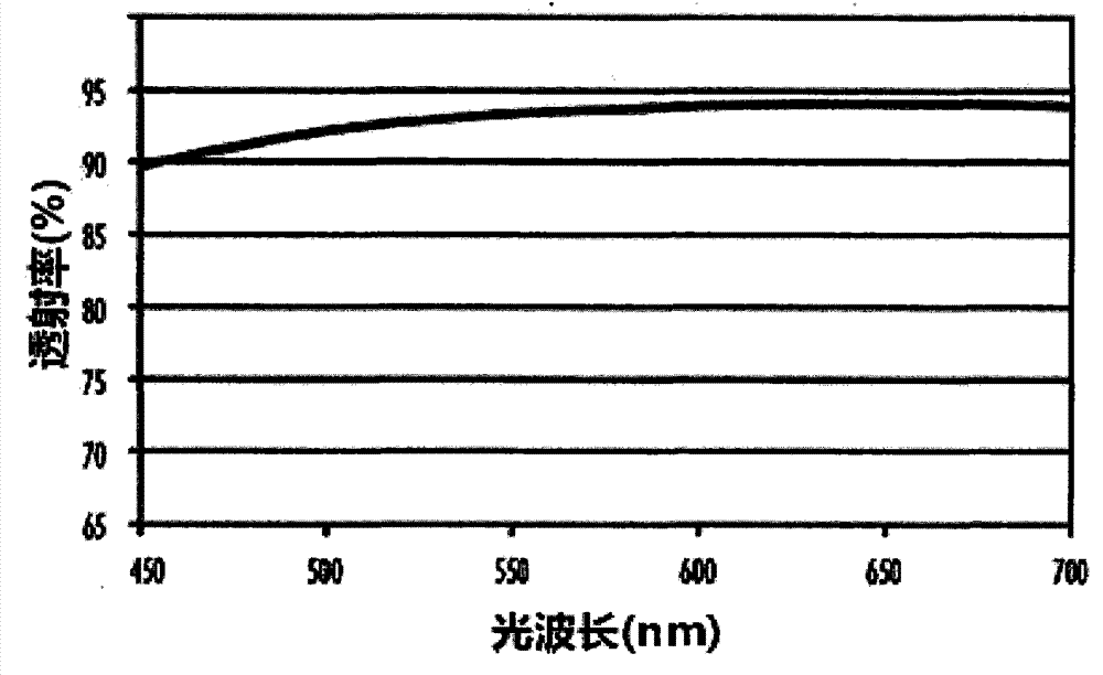
The invention relates to a preparation method for an optical thin-film of a polaroid. The method comprises the following steps: firstly, the polaroid is pre-processed; and then a nano ceramic thin-film, a nano composite metal film and a nano composite oxide film are arranged on a polaroid substrate through chemical vapor deposition, arc ion plating deposition and magnetron sputtering deposition respectively. The polaroid obtained by adopting the method is good in light transmittance, high in optical efficiency and uniform in imaging, and ensures that the definitions of images in all positions are kept the same, so that a composite three-dimensional image is free from double images and is high in contrast gradient, and accordingly, fatigue of eyes is remarkably relieved; and the surface of the polaroid has excellent heat resistance and favorable wearing resistance.

Description

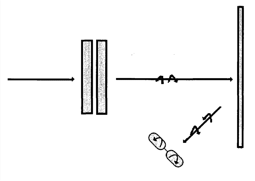
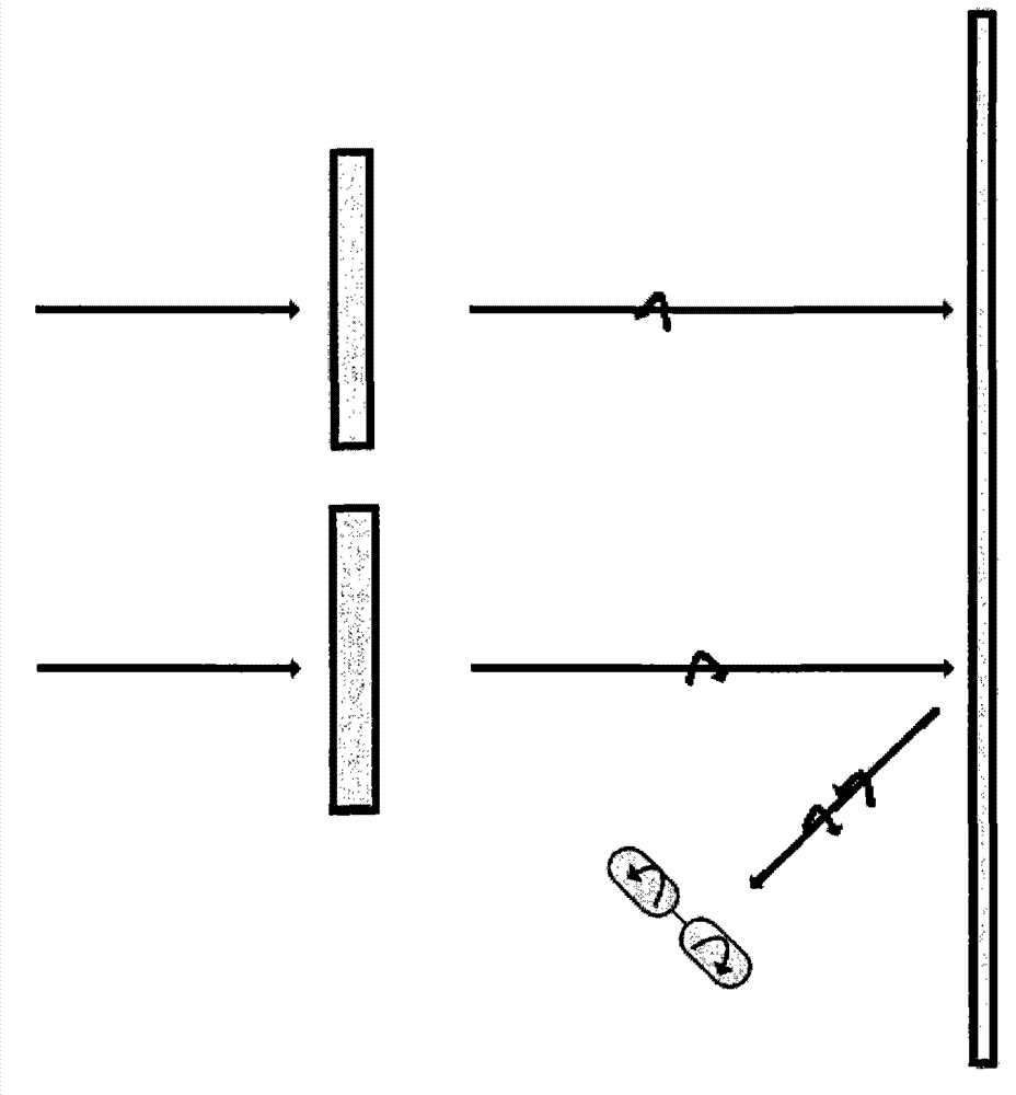
technical field [0001] The invention relates to the field of optics, and more specifically, the invention relates to a preparation method of a polarizer optical film. Background technique [0002] The principle of existing polarized stereoscopic imaging is attached Figure 1-2 As shown, different image sequences of left and right frames are output from image output devices such as projectors and projectors. After passing through left and right circular polarizers, the left and right frames that make up the image are decomposed, and the left or right frame image is modulated and coded by a polarization modulator. , encoded into one of the following three-dimensional formats: (1) the left frame image becomes left-handed polarized light, and the right frame image becomes right-handed polarized light; (2) the left frame image becomes right-handed polarized light, and the right frame image becomes right-handed polarized light. The image becomes left-handed polarized light; by wea...

Claims


Application Information

Patent Timeline
Patent Type & Authority Patents(China)
IPC IPC(8): G02B5/30G02B1/00G02B1/14G02B27/26G02B1/115G02B30/25
Inventor 郑伟军
Owner 上海图锐数码科技有限公司
Learn More