Fuel pressure waveform acquiring equipment for fuel injection system

A technology of fuel injection system and fuel pressure, which is applied to fuel injection device, fuel injection control, charging system, etc., can solve the problem that the pressure waveform W cannot be accurately obtained.

Inactive Publication Date: 2013-08-14
DENSO CORP
View PDF7 Cites 0 Cited by
  • Summary
  • Abstract
  • Description
  • Claims
  • Application Information

AI Technical Summary

Problems solved by technology

[0006] However, the inventors of the present application have found through various experiments that the pressure caused only by the n-th stage injection (target injection) cannot be accurately acquired by simply subtracting the model waveform CALn-1 from the detected pressure waveform W. Waveform Wn

Method used


Image

  • Fuel pressure waveform acquiring equipment for fuel injection system
  • Fuel pressure waveform acquiring equipment for fuel injection system
  • Fuel pressure waveform acquiring equipment for fuel injection system

Examples


Embodiment Construction

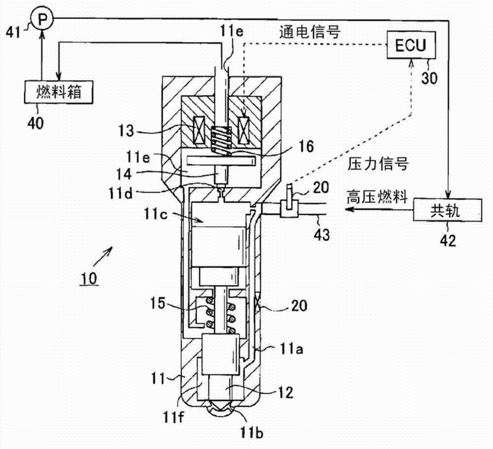
[0045] figure 1 The structure of a fuel injection system for a vehicle-mounted internal combustion engine is schematically shown, and the system includes a fuel pressure waveform acquisition device according to an embodiment of the present invention. In this embodiment, the internal combustion engine is a diesel engine having cylinders #1 to #4 for performing compression auto-ignition combustion. The fuel injection system operates to inject high-pressure fuel into cylinders #1 to #4.

[0046] exist figure 1 In, reference numeral 10 denotes a fuel injection valve mounted on each cylinder #1 to #4, 20 denotes a fuel pressure sensor mounted on the fuel injection valve 10, and 30 denotes an ECU (Electronic Control Unit) mounted on the vehicle ) 30. The fuel pressure waveform acquisition means is implemented by the ECU 30 . The fuel injection system operates such that fuel stored in a fuel tank 40 is fed to a common rail 42 as an accumulator through a high pressure pump 41 an...


PUM


Abstract

A fuel pressure waveform acquiring equipment comprises the following components: a pressure waveform acquiring device which is used for acquiring a first pressure waveform detected through a fuel pressure sensor as a multi-segment injection pressure waveform that occurs in performing multi-segment fuel injection; a model waveform storing device which is used for storing a standard model waveform as a second pressure waveform, wherein the second pressure waveform occurs when target injection which is earlier than a second segment or a later period in the multi-period ejection is performed imaginarily; a waveform extracting device which is used for subtrating the model waveform from the multi-segment injection pressure waveform for extracting a third pressure waveform that is caused by the target injection; and a compensating device which is used for compensating the model waveform through damping the model waveform for a certain damping value, wherein the damping value depends on injection interval between the earlier injection and the target injection.

Description

technical field [0001] The present invention relates to a device for acquiring, as a pressure waveform, a temporal change in fuel pressure caused by fuel injection from a fuel injection valve of an internal combustion engine. Background technique [0002] In order to precisely control the output torque and discharge state of the internal combustion engine, it is necessary to control the injection state including the injection amount and injection timing of fuel injected from the injection hole of the fuel injection valve. Japanese Patent Application Laid-Open Nos. 2010-3004 (Patent Document 1) and 2009-57924 (Patent Document 2) describe the use of a fuel pressure sensor to detect pressure in a fuel supply passage leading to a fuel injection hole caused by fuel injection. A technique that changes the fuel pressure over time to thereby detect the actual fuel injection state. [0003] For example, the actual fuel injection start timing can be detected by detecting the timing a...

Claims


Application Information

Patent Timeline
IPC IPC(8): F02D41/38F02D45/00F02M55/02G05B13/02
CPCF02D2200/0616F02D2200/0618F02D41/402Y02T10/44F02D41/3836F02D2250/04F02D2200/0602Y02T10/40
Inventor 野野山由晴山田直幸
Owner DENSO CORP
Why Eureka
Try Eureka