
Annular engine

A technology of engines and rings, which is applied in the direction of combustion engines, machines/engines, internal combustion piston engines, etc., can solve the problems of complicated structural systems, many parts, and few times of work, so as to achieve fuel utilization and overall mechanical performance. The effect of compact structure and uniform output power

Inactive Publication Date: 2013-08-14
廖荣龙
View PDF7 Cites 4 Cited by
  • Summary
  • Abstract
  • Description
  • Claims
  • Application Information

AI Technical Summary

Problems solved by technology

Although the piston engine has mature technology and has been used for a long time, it has disadvantages such as complicated structural system, many parts, large vibration during operation, large operating loss, few times of work in a single rotation cycle, and low efficiency.

Method used


Image

  • Annular engine
  • Annular engine
  • Annular engine

Examples


Embodiment Construction

[0028] The present invention will be described in detail below in conjunction with the accompanying drawings and specific embodiments.

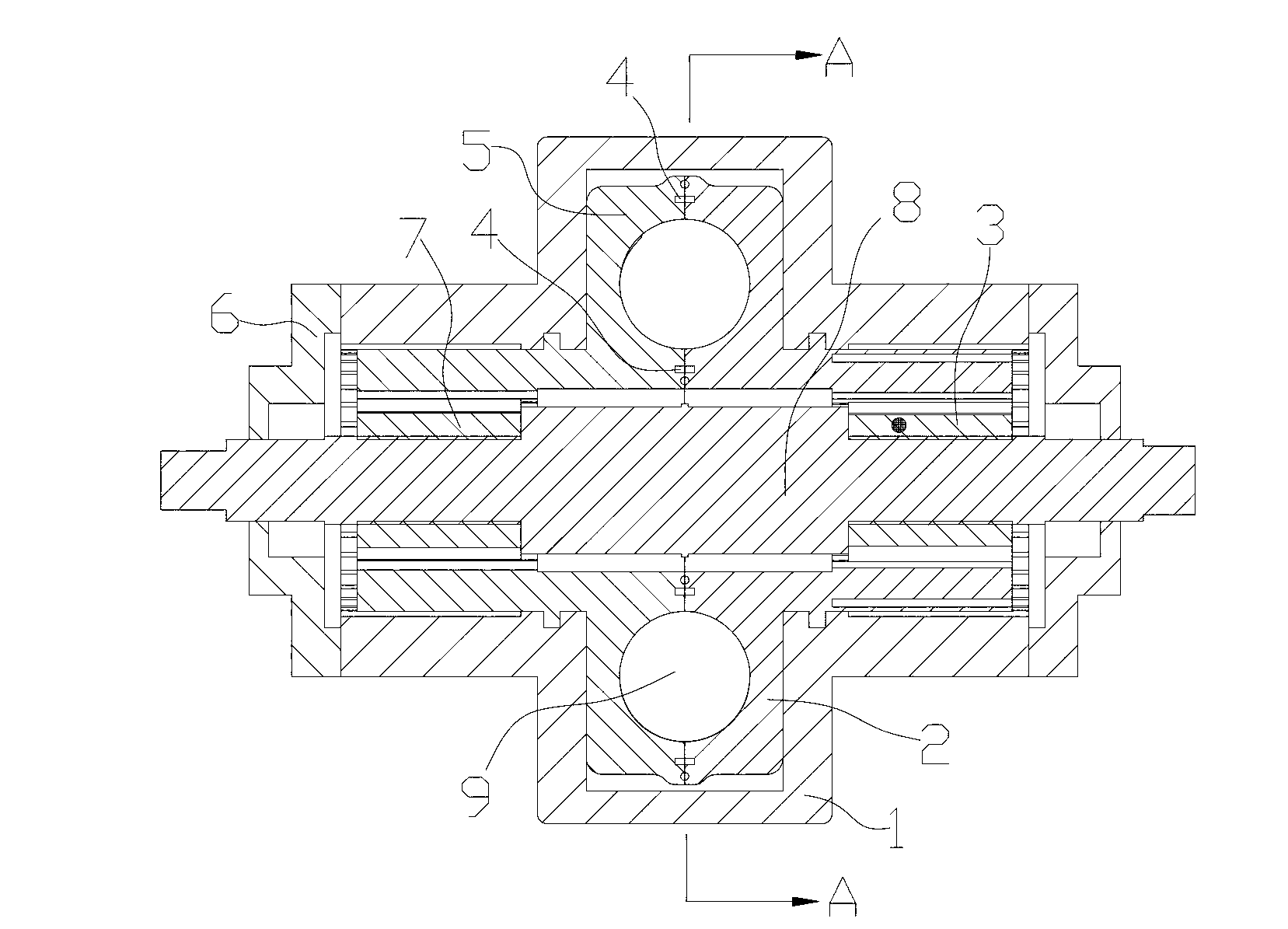
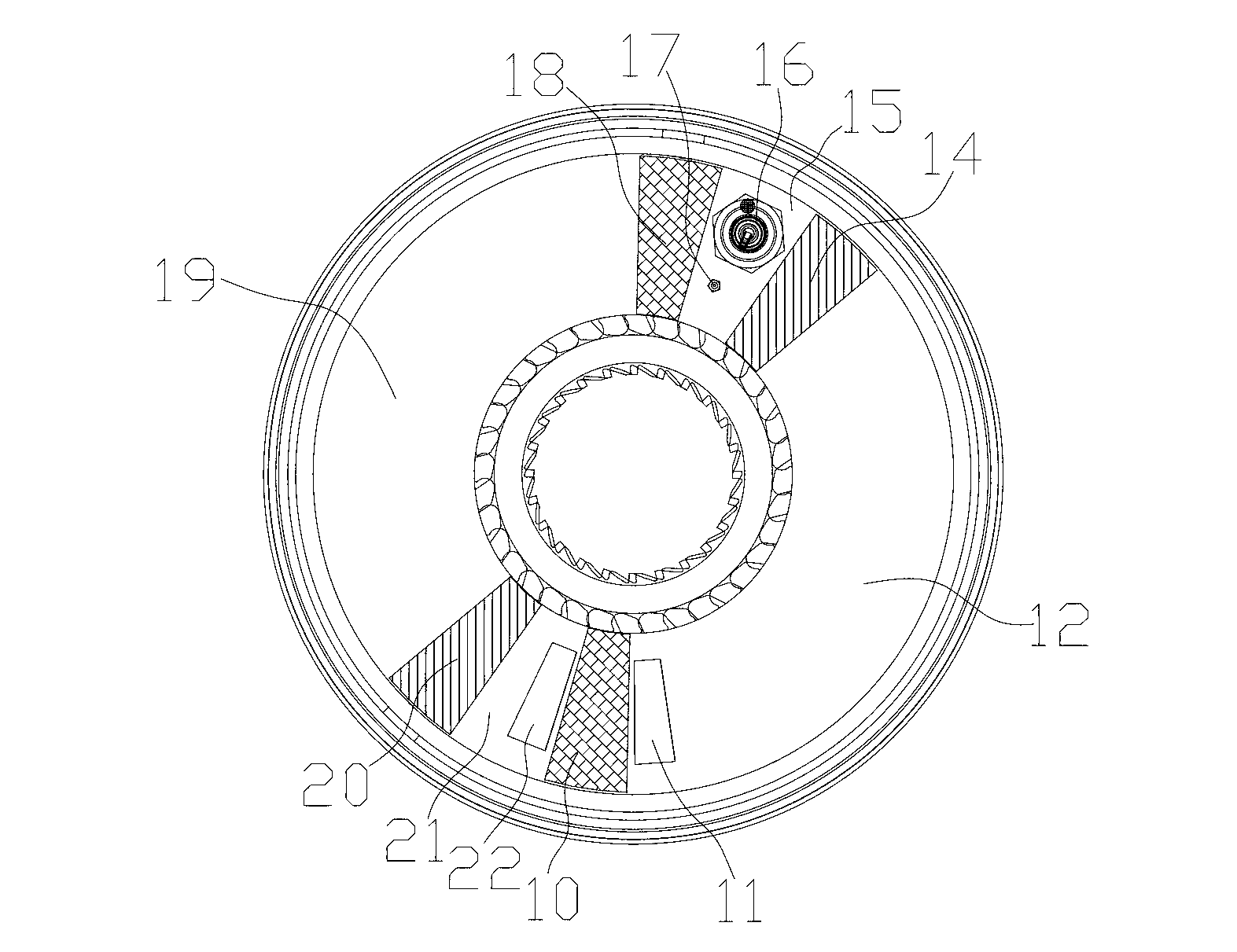
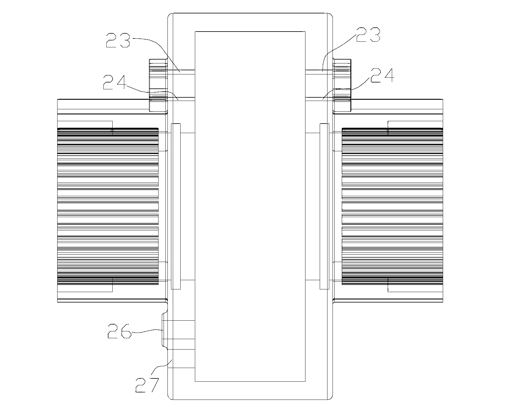
[0029] ring engines, such as figure 1 , figure 2 , image 3 , Figure 7 and Figure 9 As shown, it includes a first rotating body 5 and a second rotating body 2, the first rotating body 5 is provided with at least two rotating body blades (10, 18), and the second rotating body 2 is provided with at least two rotating body blades (14, 20), the first rotator 5 and the second rotator 2 are in an articulated connection that can rotate relative to each other, and a rotor blade is arranged between the first rotator 5 and the second rotator 2 (10, 18, 14, 20) rotating ring body cavity 9, the above-mentioned four rotating body blades (10, 18, 14, 20) divide the ring body cavity 9 into four airtight spaces that can change dynamically , the first rotating body 5 and / or the second rotating body 2 are connected to the power output shaft 8 through t...


PUM


Abstract

The invention discloses an annular engine which comprises a first rotating body and a second rotating body. The first rotating body is provided with at least two rotating body blades, the second rotating body is provided with at least two rotating body blades, the first rotating body and the second rotating body can be connected in a relatively rotating mode, an annular cavity for accommodating the rotating body blades to rotate is arranged between the first rotating body and the second rotating body, the four rotating body blades enable the annular cavity to be divided into at least four enclosed spaces capable of changing dynamically, and the first rotating body and / or the second rotating body are or is respectively connected with a power output shaft through ratchet wheels. The annular engine has the advantages of being compact in structure, small in vibration, high in efficiency, stable in operation, convenient to maintain and excellent in mechanical performance. Compared with an existing engine, fuel availability and whole mechanical performance of the annular engine are improved greatly.

Description

technical field [0001] The invention relates to the field of various power supply equipment applied to various motor vehicles and factory power systems as well as actual production, and is specifically a ring engine. Background technique [0002] The existing four-stroke piston reciprocating piston engines on the market are composed of pistons, crankshafts, connecting rods, valves and other components, which perform four independent strokes of air intake, compression, combustion, and exhaust in the same cylinder. The generated pressure drives the piston to reciprocate, and the crankshaft is driven by the piston connecting rod to convert the reciprocating motion into rotation. Although the piston engine has mature technology and has been used for a long time, it has disadvantages such as complicated structural system, many parts, large vibration during operation, large operating loss, few times of work in a single rotation cycle, and low efficiency. Contents of the inventio...

Claims


Application Information

Patent Timeline
Patent Type & Authority Applications(China)
IPC IPC(8): F02B53/00
CPCY02T10/17Y02T10/12
Inventor 廖荣龙
Owner 廖荣龙
Learn More