Server cabinet cable storage rack

A technology for server cabinets and storage racks, which is applied in the field of server cabinet cable storage racks, can solve the problems of difficult cable combing and identification, and achieve the effects of simple structure, convenient installation, and easy combing

Active Publication Date: 2015-07-22
STATE GRID CORP OF CHINA +1
View PDF5 Cites 0 Cited by
  • Summary
  • Abstract
  • Description
  • Claims
  • Application Information

AI Technical Summary

Problems solved by technology

[0003] The present invention provides a server cabinet cable storage rack, which solves the problem that the existing server cabinet cables are not easy to comb and identify the cables

Method used


Image

  • Server cabinet cable storage rack
  • Server cabinet cable storage rack
  • Server cabinet cable storage rack

Examples


Embodiment Construction

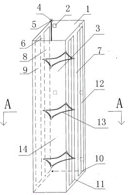
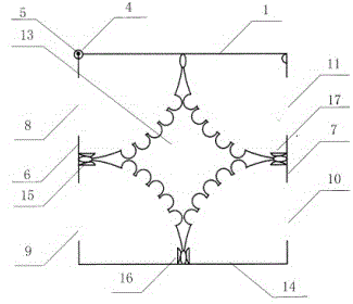
[0012] A server cabinet cable storage rack, comprising a rectangular backboard 1, a backboard fixing screw hole 2 is arranged on the rectangular backboard, a rotating shaft seat 4 is arranged on the left side of the backboard, and a rotating shaft seat 4 is movable in the rotating shaft seat 4 The rotating shaft 5 is fixedly connected to the rear side of the left side 6 of the U-shaped cover 3, and the first cable plug inlet and outlet 8 and the second cable plug inlet and outlet are respectively provided on the left side 6 of the U-shaped cover 3. 9. On the right side 7 of the U-shaped cover 3, the third cable plug inlet and outlet 10 and the fourth cable plug inlet and outlet 11 are respectively provided, and the inner side of the left side 6 of the U-shaped cover 3 is provided with a vertical vertical direction The left draw-in groove 15 is provided with the front draw-in groove 16 of the vertical direction up and down in the inboard of the front panel 14 of the U-shaped cov...


PUM


Abstract

The invention discloses a server cabinet cable storage rack which solves the problem that existing server cabinet cables are difficult to card and mark. The server cabinet cable storage rack comprises a rectangular back plate (1), a rotating shaft seat (4) and a rotating shaft (5) are arranged at the left side edge of the back plate, the rotating shaft (5) is fixedly connected with a rear side edge of a left side face (6) of a U-shaped cover (3), a left clamping groove (15) in a vertical direction is arranged on the inner side of each of three side faces of the U-shaped cover (3), a clamping joint (18) is arranged on each of four vertical angles of a diamond cable clamping plate (13), a cable clamping groove (19) is arranged at each of four edges of each diamond cable clamping plate (13), and the diamond cable clamping plates (13) are clamped together with the left clamping groove (15), a front clamping groove (16) and a right clamping groove (17) respectively through the clamping joints on the three vertical angles. The server cabinet cable storage rack is simple in structure, convenient to mount, and applicable to mounting and use of and various cabinets.

Description

technical field [0001] The invention relates to a server cabinet cable storage rack, which can centrally arrange and store various cables such as power lines, network cables, and optical fibers connected to the server on the back side of the cabinet, and is convenient for combing and marking of the cables. Background technique [0002] At present, all kinds of server cabinets do not have special equipment for centrally arranging, sorting, and storing cables. Most power cables, network cables, and optical fibers are bound to the frame on the rear side of the cabinet with cable ties, and then connected to the server. The cables are exposed. In the cabinet, this is not conducive to the combing and identification of cables, and affects the appearance of the cabinet interior, but also easily causes the cables to be accidentally pulled and damaged during operations such as maintenance and disassembly of servers in the cabinet; When the cable is connected to the position, the cab...

Claims


Application Information

Patent Timeline
Patent Type & Authority Patents(China)
IPC IPC(8): B65H75/16
Inventor 孙刚么利中周自强
Owner STATE GRID CORP OF CHINA
Why Eureka
Try Eureka