Knurl wheel

A technology of knurling wheels and rollers, which is applied in decorative arts, embossed ornaments, etc., can solve the problems of workpiece displacement, defective products, processing errors, etc., and achieve the effects of avoiding workpiece displacement, high authenticity rate, and simple structure

Inactive Publication Date: 2013-08-14
SUZHOU CHUANGFENG PRECISION HARDWARE
View PDF6 Cites 6 Cited by
  • Summary
  • Abstract
  • Description
  • Claims
  • Application Information

AI Technical Summary

Problems solved by technology

This kind of tool needs to apply an additional force relative to the workpiece. In the process of frequent processing, this force will cause the workpiece to shift, resulting in machining errors and even defective products.

Method used


Image

  • Knurl wheel

Examples


Embodiment Construction

[0010] Specific embodiments of the present invention will be further described in detail below.

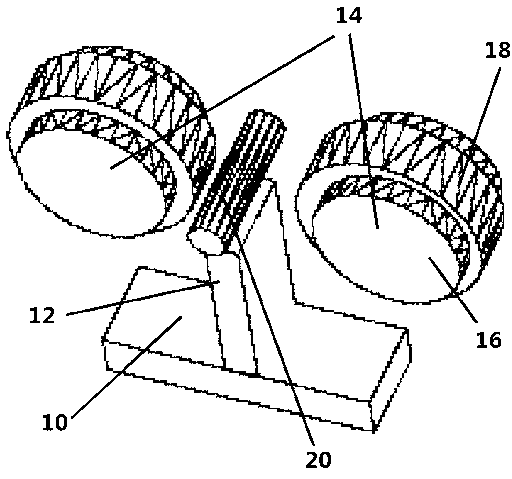
[0011] like figure 1 As shown, the knurling wheel 14 of the present invention includes a base 10, a platform 12 of a workpiece 20 is arranged in the middle of the base 10, and two knurling wheels 14 are symmetrically arranged on both sides of the platform 12 of the workpiece 20. The axes of the two knurl wheels 14 are parallel to each other. The two knurling wheels 14 both include a rotating shaft 16 and a roller 18 arranged outside the rotating shaft 16 , the roller 18 is coaxial with the rotating shaft 16 and the outer part of the roller 18 is provided with patterns.

[0012] When the present invention is in use, the workpiece 20 to be processed is placed on the workpiece 20 platform 12, and the motor drives the two knurling wheels 14 to rotate in the same direction to form a squeeze on the workpiece 20, so that patterns can be formed on the surface of the workpiece 20.

[001...


PUM


Abstract

The invention discloses a knurl wheel which comprises a base and is characterized in that two rotatable knurl wheel bodies with axes parallel to each other are arranged on the base. The two knurl wheel bodies respectively squeeze a workpiece from two opposite square parts and effectively prevent workpiece shifting. The knurl wheel has the advantages of being simple in structure, high in rate of qualified products and the like.

Description

technical field [0001] The invention relates to a machining tool, especially a machining tool for knurling. Background technique [0002] Knurling is a process of embossing patterns on the surface of a workpiece with a knurling tool. Currently, knurling tools generally include a knurling wheel that is pressed against the workpiece and then rotated to form a pattern on the workpiece. This kind of tool needs to apply an additional force relative to the workpiece. In the process of frequent machining, this force will cause the workpiece to shift, resulting in machining errors and even defective products. [0003] Contents of the invention [0004] In order to overcome this problem, the present invention provides a knurling wheel with simple structure and high authenticity rate. [0005] The technical solution of the present invention is to provide a knurling wheel, which includes a base, and is characterized in that: the base is provided with two rotatable knurling wheels ...

Claims


Application Information

Patent Timeline
IPC IPC(8): B44B5/02
Inventor 徐德明
Owner SUZHOU CHUANGFENG PRECISION HARDWARE
Why Eureka
Try Eureka