Anti-rotating condenser welding process

A welding process and condenser technology, which is applied in the welding process field of automotive condensers, can solve problems such as welding failure, deviation, affecting the quality and appearance of the condenser, and achieve the effect of improving quality and ensuring installation size

Inactive Publication Date: 2013-08-14
JIANGSU JIAHE THERMAL SYST RADIATOR
View PDF0 Cites 2 Cited by
  • Summary
  • Abstract
  • Description
  • Claims
  • Application Information

AI Technical Summary

Problems solved by technology

[0002] The vehicle condenser includes flat tubes, fins, support plates and liquid collection pipes, the flat pipes and fins are arranged at intervals, the support plate and the liquid collection pipes, the two ends of the flat pipes are inserted into the liquid collection pipes, and the liquid collection pipes The tube is welded with a pressure plate and a bracket, and there is a gap between the flat tube and the liquid collecting pipe. When the core body composed of the flat tube and the fins is inserted into the liquid collecting pipe and enters the brazing furnace for overall brazing, the liquid collecting pipe is placed on the pressure plate and the bracket. Rotating the liquid collecting pipe under the action of gravity may cause the flat pipe to separate from the liquid collecting pipe, lead to welding failure, increase the size of the core body, change the space position of the pressure plate and the bracket, that is, the installation size changes, and the diagonal angle of the core body changes. There is a large deviation of the line, which seriously affects the quality and appearance of the condenser

Method used


Image

  • Anti-rotating condenser welding process

Examples


Embodiment Construction

[0012] Below in conjunction with accompanying drawing and specific embodiment, further illustrate the present invention, it should be understood that these embodiments are only used to illustrate the present invention and are not intended to limit the scope of the present invention, after reading the present invention, those skilled in the art will understand various aspects of the present invention Modifications in equivalent forms all fall within the scope defined by the appended claims of this application.

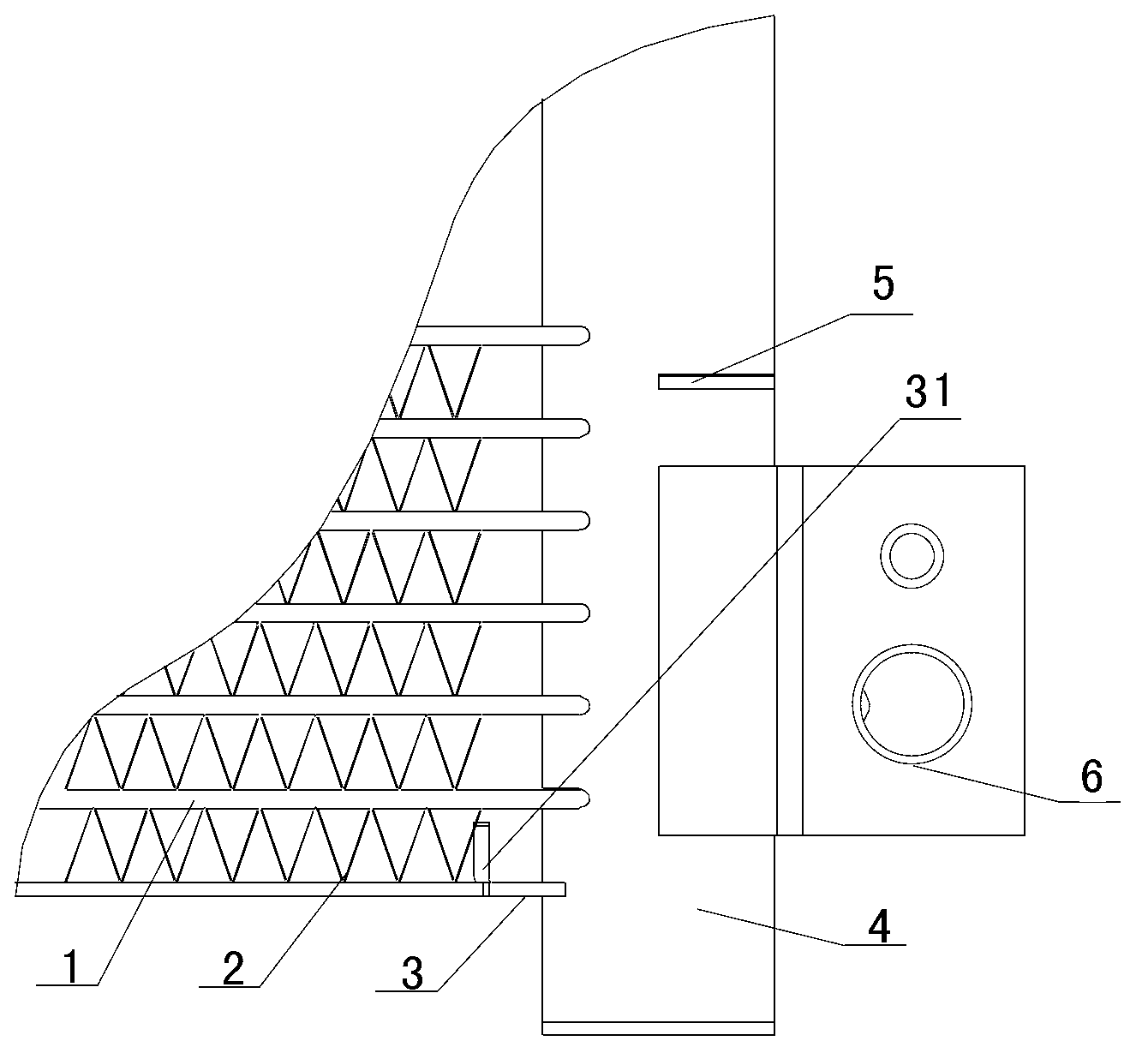
[0013] Such as figure 1 As shown, a condenser includes a core body and a liquid collecting pipe 4, including a core body including flat tubes 1 and fins 2, the flat tubes 1 and fins 2 are arranged at intervals, and a support plate 3 is provided at the bottom The two ends of the flat tube 1 are inserted into the liquid collecting pipe, the fins 2 are arranged between the support plate 3 and the flat tube, and the inside of the end of the support plate 3 is provided with ...


PUM


Abstract

The invention discloses an anti-rotating condenser welding process. A condenser comprises a core and a liquid collecting pipe, the core comprises flat pipes and fins which are arranged at intervals, a support plate is arranged at the bottom of the core, and two ends of each flat pipe are inserted into the liquid collecting pipe. The welding process includes the steps: firstly, preliminarily fixing two ends of the support plate and the liquid collecting pipe by spot welding; and secondly, placing the spot-welded condenser into a brazing furnace for integral brazing. By the aid of the anti-rotating condenser welding process, the support plate and the liquid collecting pipe are preliminarily fixed by spot welding to form a frame, the core comprising the flat pipes and the fins is stably kept in the frame, the flat pipes are constantly inserted into the liquid collecting pipe when the condenser is placed into the brazing furnace for brazing, welding strength of the flat pipes and the liquid collecting pipe is ensured, uniformity of the diagonal size of the core is effectively controlled, rotation of the liquid collecting pipe is prevented by preliminary spot-welding fixing, mounting sizes of a pressing plate and a support are ensured, and the quality of the condenser is improved.

Description

technical field [0001] The invention relates to a welding process for a vehicle condenser. Background technique [0002] The vehicle condenser includes flat tubes, fins, support plates and liquid collection pipes, the flat pipes and fins are arranged at intervals, the support plate and the liquid collection pipes, the two ends of the flat pipes are inserted into the liquid collection pipes, and the liquid collection pipes The tube is welded with a pressure plate and a bracket, and there is a gap between the flat tube and the liquid collecting pipe. When the core body composed of the flat tube and the fins is inserted into the liquid collecting pipe and enters the brazing furnace for overall brazing, the liquid collecting pipe is placed on the pressure plate and the bracket. Rotating the liquid collecting pipe under the action of gravity may cause the flat pipe to separate from the liquid collecting pipe, lead to welding failure, increase the size of the core body, change the...

Claims


Application Information

Patent Timeline
Patent Type & Authority Applications(China)
IPC IPC(8): B23K1/008
Inventor 李宝民马树洋
Owner JIANGSU JIAHE THERMAL SYST RADIATOR
Why Eureka
Try Eureka