Head for cutting machine and cutting machine

A cutting machine and machine head technology, which is applied in the direction of cutting tools for shearing machine devices, metal processing machinery parts, feeding devices, etc. Knife repositioning and other issues to achieve the effect of improving service life and convenient installation

Active Publication Date: 2015-03-25
NEWONDER SPECIAL ELECTRIC
View PDF9 Cites 0 Cited by
  • Summary
  • Abstract
  • Description
  • Claims
  • Application Information

AI Technical Summary

Problems solved by technology

In the above technical solution, the cutting knife is installed on the knife holder, and the inner shoulder at the end of the knife shaft is used as the positioning surface. When installing, the thickness of the cutting knife will have a great impact on the gap between the two blades. , therefore, the requirements for the cutter are higher, which increases the cost and the difficulty of installation
Moreover, this structure makes it difficult to reposition the upper and lower cutters after the cutter is worn
Thus affecting the service life of the cutter

Method used


Image

  • Head for cutting machine and cutting machine
  • Head for cutting machine and cutting machine
  • Head for cutting machine and cutting machine

Examples


Embodiment Construction

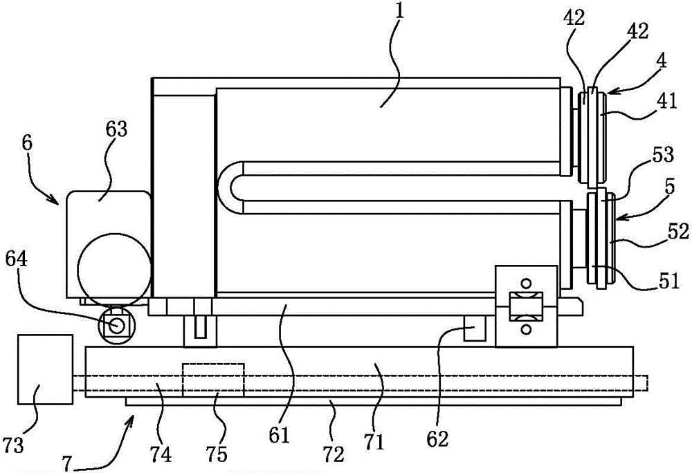
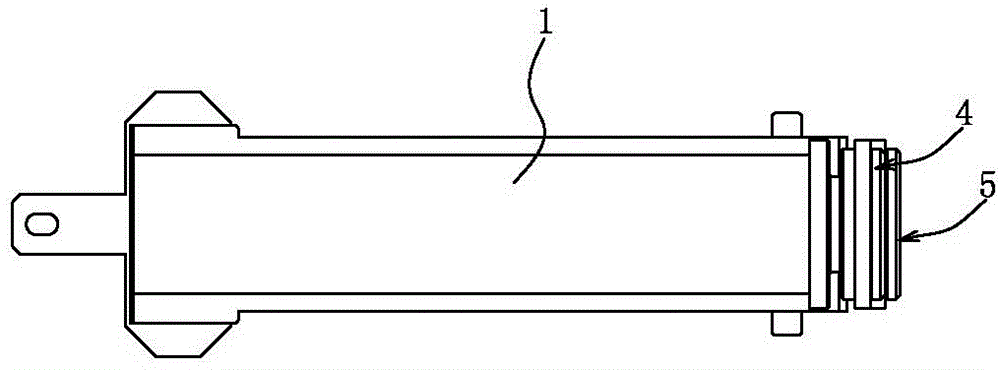
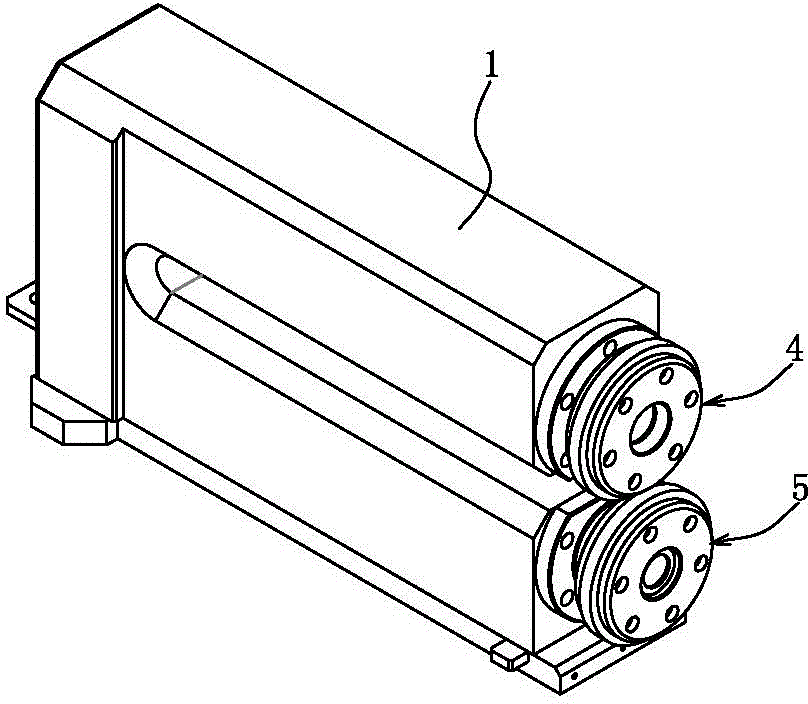
[0024] see Figure 1 to Figure 6 , a kind of embodiment that is used for the machine head of cutting machine that the present invention provides, comprises a tool head frame 1, the first main shaft 2 and the second main shaft 3 that are installed on the described tool head frame 1, are arranged on the The inner cutter head 4 at the end of the first main shaft 2 and the outer cutter head 5 arranged at the end of the second main shaft 3, the inner cutter head 4 includes a reference positioning plate 41 fixed on the end surface of the first main shaft 2 , the pressing plate 42 set on the end of the first main shaft 2 and the inner blade 43 between the reference positioning plate 41 and the pressing plate 42, the outer cutter head 5 includes a The reference positioning ring 51 at the top, the pressure ring 52 sleeved on the end of the second main shaft 3 and located outside the reference positioning ring 51 , and the outer blade 53 between the reference positioning ring 51 and the...


PUM


Abstract

A head for a cutting machine comprises a cutting head rest, a first spindle, a second spindle, an inner cutting head and an outer cutting head. The inner cutting head comprises a reference locating plate fixed on the end face of the first spindle, a press plate sleeved at the end of the first spindle and an inner blade which is located between the reference locating plate and the press plate. The outer cutting head comprises a reference locating ring, a press ring and an outer blade, wherein the reference locating ring is fixed at the end of the second spindle, the press ring is sleeved at the end of the second spindle and located on the outer side of the reference locating ring, the outer blade is positioned between the reference locating ring and the press ring, an inner blade reference locating face is formed on the outer side wall of the reference locating plate, the inner blade is closely attached to the inner blade reference locating face, an outer blade reference locating face is formed on the outer side wall of the reference locating ring, and the outer blade is closely attached to the outer blade reference locating face. The gap between edges of blades cannot be affected by thicknesses of blades, so that the blades can be installed conveniently, besides, the blades can be polished again for use once abraded, and therefore, service lives of the blades are improved.

Description

technical field [0001] The invention relates to a machine head of a cutting machine for silicon steel sheets of a transformer iron core, and a cutting machine equipped with the machine head. Background technique [0002] In the prior art, such as the utility model patent whose Chinese patent number is CN98226641.3, the disclosure date is November 17, 1999, which discloses a kind of sleeve cutting type steel strip curve cutting machine. In the cutting mechanism, the upper and lower The disc cutters are respectively fixed on the upper and lower knife shafts, and the upper and lower knife shafts are respectively installed on the upper and lower knife rests by bearings, the upper knife rest is connected to the lower knife rest, and the tail ends of the upper and lower knife shafts Install the upper and lower transmission wheels, the lower tool holder is installed on the sliding seat by the rotating shaft, and the worm wheel is installed on the other end of the sliding seat, and ...

Claims


Application Information

Patent Timeline
Patent Type & Authority Patents(China)
IPC IPC(8): B23D19/04B23D35/00B23Q5/34
Inventor 谭勇张明德
Owner NEWONDER SPECIAL ELECTRIC
Why Eureka
Try Eureka