Configuration structure of a reciprocating tank of a high gradient superconducting magnetic separator
A configuration structure, superconducting magnetic technology, applied in the direction of high gradient magnetic separator, etc., to achieve the effect of improving the sorting ability, eliminating inclusions, and reducing the head
- Summary
- Abstract
- Description
- Claims
- Application Information
AI Technical Summary
Problems solved by technology
Method used
Image


Examples
specific Embodiment approach 1
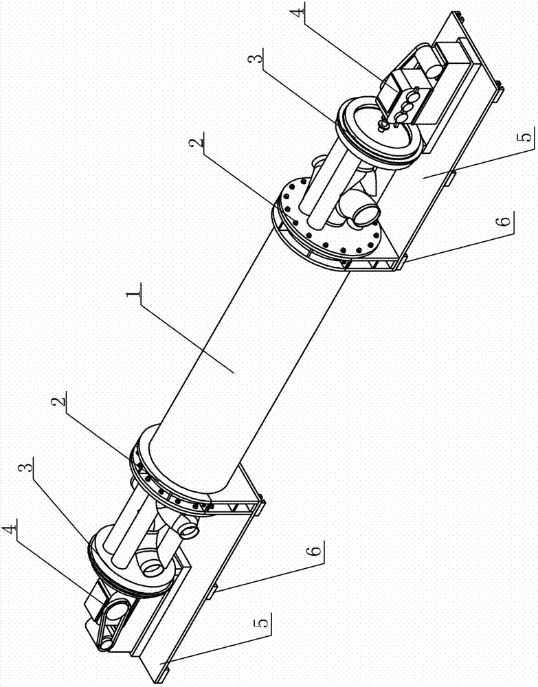
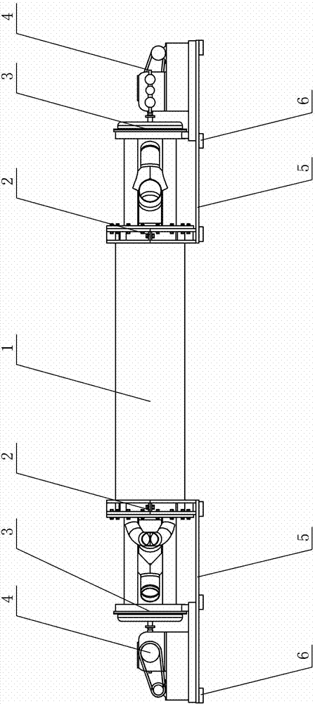
[0009] Specific implementation mode one: combine figure 1 with figure 2 Describe this embodiment, the configuration structure of a reciprocating tank of a high gradient superconducting magnetic separator described in this embodiment includes a sorting tank mechanism 1, two clamping mechanisms 2, two pulsating flow generators 3, and two pulsating mechanisms 4. Two supporting plates 5 and a plurality of moving sliders 6, the two ends of the sorting tank mechanism 1 are respectively fixed and installed on a supporting plate 5 through a clamping mechanism 2, and each supporting plate 5 is respectively installed with a The pulsating mechanism 4 is connected to the corresponding end of the sorting tank mechanism 1 through a pulsating flow generator 3 respectively, and a plurality of moving sliders 6 are arranged on the lower surface of each supporting plate 5 .
[0010] In this embodiment, the pulsation stroke of each pulsation flow generator 3 is 0-4 cm, and the pulse frequency r...
specific Embodiment approach 2
[0012] Specific implementation mode two: combination Figure 3 to Figure 8 Describe this embodiment, the sorting tank mechanism 1 of the configuration structure of a reciprocating tank of a high gradient superconducting magnetic separator described in this embodiment includes an outer cylinder 1-1, two middle cylinders 1-2, two double-row circles Ring media box assembly 1-3, two inner cylinder confluence pipes 1-4, two first outer cylinder confluence pipes 1-5, two second outer cylinder confluence pipes 1-6 and eight connecting pipes 1-7, The middle part of the outer cylinder 1-1 is provided with a central dummy area, and the two ends of the outer cylinder 1-1 are respectively provided with a middle cylinder insertion area, and each of the middle cylinder insertion areas is respectively inserted with a middle cylinder 1-2 , and the end flanges of each middle cylinder 1-2 are sealed and connected with the corresponding end face of the outer cylinder 1-1, and each middle cylinde...
specific Embodiment approach 3
[0016] Specific implementation mode three: combination Figure 5 , Figure 9 , Figure 10 with Figure 11 Describe this embodiment, the arrangement structure of reciprocating tank of a high-gradient superconducting magnetic separator described in this embodiment is provided with inner cylinder confluence space 1-2-1 in the end of each middle cylinder 1-2, and the inner cylinder The outer wall of the confluence space 1-2-1 and the inner side of the end of the middle tube 1-2 form an end dummy space 1-2-2, and the end dummy space 1-2-2 and the end of the middle tube 1-2 The opposite side of the flange, the inner side of the flange at the end of the middle cylinder 1-2, and the inner wall of the middle cylinder 1-2 form the end confluence space 1-2-3, and each inner cylinder confluence space 1-2-1 is It communicates with the corresponding inner barrel confluence pipe 1-4, and each end dummy space 1-2-2 communicates with the corresponding connecting pipe 1-7, and each end confl...
PUM
 Abstract
Description
Claims
Application Information
 - R&D
- Intellectual Property
- Life Sciences
- Materials
- Tech Scout
- Unparalleled Data Quality
- Higher Quality Content
- 60% Fewer Hallucinations
Browse by: Latest US Patents, China's latest patents, Technical Efficacy Thesaurus, Application Domain, Technology Topic, Popular Technical Reports.
© 2025 PatSnap. All rights reserved.Legal|Privacy policy|Modern Slavery Act Transparency Statement|Sitemap|About US| Contact US: help@patsnap.com