
Conditioner

A conditioner and rotor technology, applied in the field of conditioners, can solve the problems of increasing equipment manufacturing and installation costs, uneven discharge, and reducing aging effects, so as to reduce equipment manufacturing and installation costs and reduce equipment occupation. Good effect of space and aging effect

Active Publication Date: 2013-08-14
牧羊有限公司
View PDF6 Cites 5 Cited by
  • Summary
  • Abstract
  • Description
  • Claims
  • Application Information

AI Technical Summary

Problems solved by technology

[0006] 1. The steam nozzles are arranged at fixed points, and the injection surface is small, which cannot guarantee complete and direct contact with all materials, and the conditioning effect is not good.
[0007] 2. In order to maximize the effective contact between the material and the steam, the blade speed must be greatly increased in order to completely throw the material up and fill the entire cavity; the increase in the blade speed will greatly increase the rotating drive power and increase the energy consumption
[0008] 3. The increase of the paddle speed will shorten the residence time of the material in the cylinder and reduce the curing effect. The commonly used method is to increase the length or quantity of the tempering cylinder, which increases the cost of equipment manufacturing and installation, and is inconvenient to maintain.
[0009] 4. The material reaches the outlet under the propulsion of the paddle, and falls naturally by its own gravity. The material is not uniform, which leads to unstable working current of the granulator and a decrease in output.

Method used


Image

  • Conditioner
  • Conditioner
  • Conditioner

Examples


Embodiment Construction

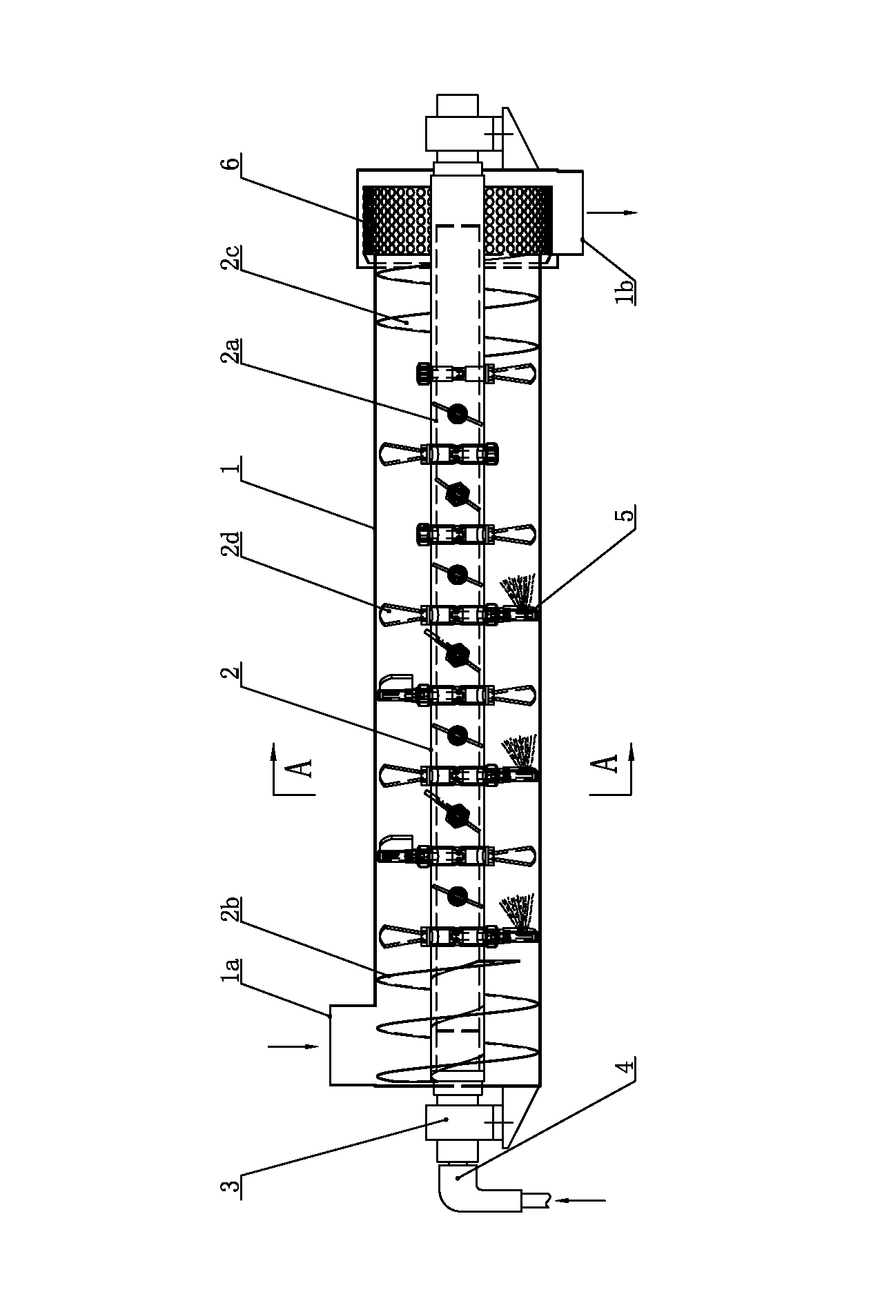
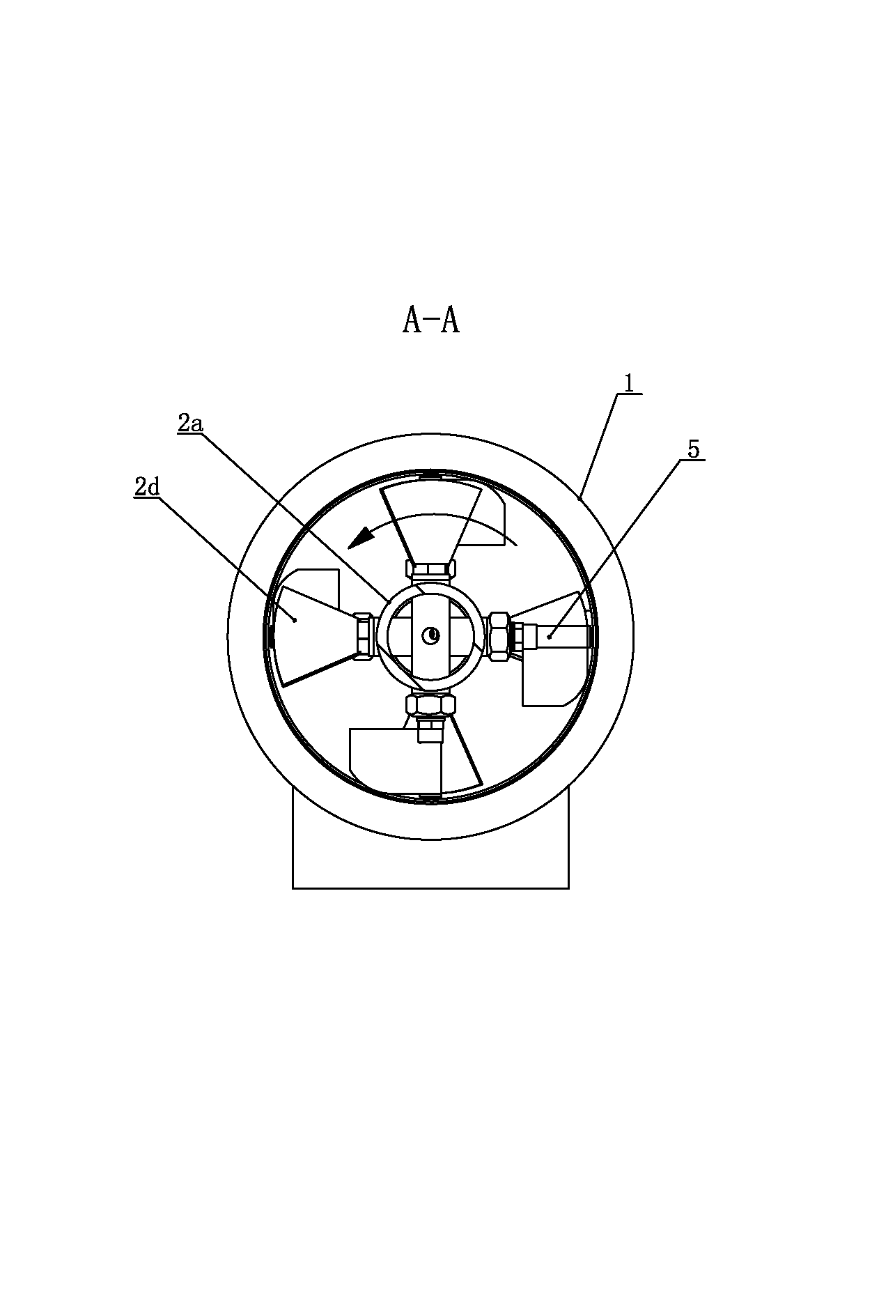
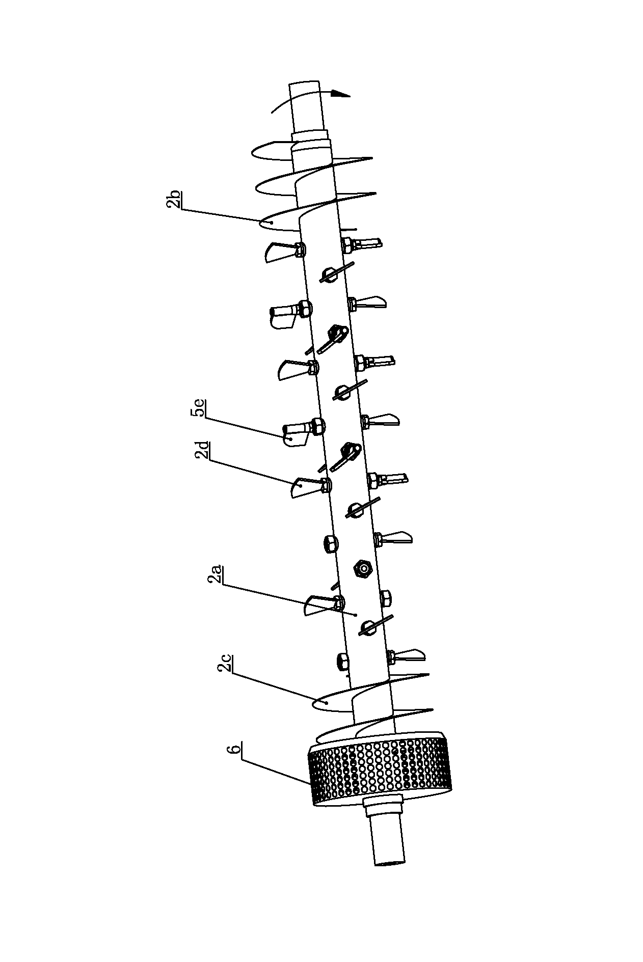
[0025] Such as Figure 1 to Figure 3 As shown, the conditioner of the present invention includes a cylinder body 1, a rotor 2 for mixing materials is installed in the cylinder body 1, and both ends of the rotor 2 are respectively supported on the machine frame through bearing seats 3. The rotor 2 includes a rotor main shaft 2a and propulsion paddles 2d evenly distributed on the rotor main shaft 2a to stir and propel materials. The upper part of one end of the cylinder 1 is provided with a feed port 1a, and the lower part of the other end of the cylinder 1 is provided with a discharge port 1b. A feed-end helical blade 2b is installed on the rotor main shaft 2a near the feed inlet, and a discharge-end helical blade 2c is installed on the rotor main shaft 2a near the discharge port. The feed-end helical blade 2b and the discharge-end helical blade 2c are both full helical structure. The rotor shaft on the outside of the spiral blade 2c at the discharge end is equipped with a uni...


PUM


Abstract

The invention relates to a conditioner. A full spiral blade is mounted at two ends of a rotor spindle respectively, a uniformizing unit is sleeved on the rotor spindle outside the spiral blade at the discharging end, the rotor spindle is in a hollow structure, a steam rotary joint is mounted at one end of the rotor spindle, propelling blades are fixedly connected to one end of blade casing tubes, the other ends of the blade casing tubes are radially inserted in the rotor spindle, and steam injection units are uniformly mounted on the rotor spindle within a certain length range at the feeding end. Blade shafts of the steam injection units are inserted in the blade casing tubes, roots of steam nozzles are inserted in the blade shafts, nozzle casing tubes are sleeved at free ends of the steam nozzles, steam on-off blades are perpendicularly connected onto the nozzle casing tubes, and steam is injected when the steam on-off blades rotate to be parallel with the axis of the rotor spindle. By means of the conditioner, steam and materials can be uniformly mixed, the steam utilization rate is improved, the equipment energy consumption and the manufacture cost are reduced, the conditioning effect is improved, and the discharge is uniform.

Description

technical field [0001] The invention relates to a conditioner, which is used for curing powder in the front of a granulator or an extruder, and belongs to the technical field of food or feed machinery. Background technique [0002] The main equipment for pellet feed production is pellet mill and extruder, both of which must be equipped with various types of conditioners. Conditioning is a key link in feed processing, and the quality of feed conditioning is directly related to the finished product. the quality of. [0003] The traditional conditioner includes a cylinder, in which a rotor for stirring materials is installed. The rotor includes a main shaft of the rotor and propulsion paddles evenly distributed on the main shaft of the rotor to stir and propel the materials. The lower part of the other end is provided with a discharge port, the feed end helical blade is installed on the rotor main shaft near the feed port, and the discharge end helical blade is installed on th...

Claims


Application Information

Patent Timeline
IPC IPC(8): A23N17/00A23P1/02A23P1/14A23P10/20A23P30/30
Inventor 闾宏范文海李庆凯姜明明
Owner 牧羊有限公司
Learn More