
Method for measuring loss of magnetic element

A technology of magnetic components and measurement methods, which is applied in the direction of magnetic performance measurement, measurement devices, and measurement of electrical variables, etc., can solve the problems of measurement accuracy stray loss, time-consuming, and inability to measure excitation waveforms, and achieve convenient and simple measurement, low cost, and The effect of overcoming the influence of stray parameters on measurement accuracy

Active Publication Date: 2013-07-31
FUZHOU UNIV
View PDF4 Cites 22 Cited by
  • Summary
  • Abstract
  • Description
  • Claims
  • Application Information

AI Technical Summary

Problems solved by technology

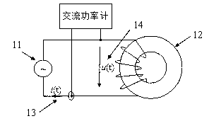
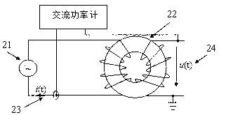
[0006] In summary, the measurement accuracy of the AC power meter method is affected by the impedance angle of the measured magnetic element. Although the DC power meter method fundamentally overcomes the sensitivity of the measurement error of the AC power meter method to the impedance angle of the measured magnetic element, However, its measurement accuracy is affected by the stray losses of power converter circuit components
In terms of measurement principles, these two methods are based on obtaining the loss of the magnetic component under test from the input power, which inevitably has two problems. One is to obtain the loss of the magnetic component under test based on the absolute power measurement. Therefore, it is necessary to compensate the errors through a cumbersome calibration process; second, it is impossible to measure complex excitation waveforms under actual working conditions, such as the voltage at both ends of the input inductor of a power factor correction circuit (PFC) Magnetic component losses under excitation
The calorimeter method is generally only suitable for laboratory research because of its tediousness and time-consuming

Method used


Image

  • Method for measuring loss of magnetic element
  • Method for measuring loss of magnetic element
  • Method for measuring loss of magnetic element

Examples


Embodiment Construction

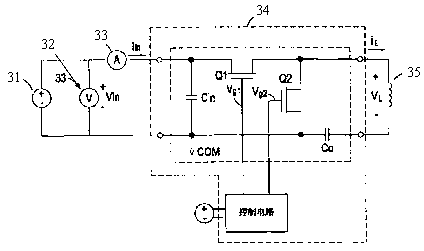
[0029] The magnetic element loss measurement method of the present invention, such as Figure 5 As shown, a power converter is used as the test circuit, the input power of the test circuit is measured under working conditions, and then the two ends of the magnetic element in the test circuit are selected, such as the two ends of the inductor L or the primary or secondary of the transformer TX Connect the two ends of the side winding, and connect the tested magnetic element in parallel at the two ends, then measure the input power of the test circuit after the tested magnetic element is connected in parallel, and the difference between the input power of the test circuit before and after the parallel test magnetic element is Is the loss of the tested magnetic component under working conditions. The embodiments using BUCK circuit, flyback circuit, and active power factor correction circuit as test circuits are as follows: Figure 8 , 9 , 10 shown.

[0030] In order to make the test...


PUM


Abstract

The invention relates to a method for measuring a loss of a magnetic element. The method comprises the steps that a power converter serves as a test circuit; input power of the test circuit is measured under a working condition; two end points of a magnetic element in the test circuit are selected; the measured magnetic element is connected in parallel with the two end points; then input power of the test circuit after the measured magnetic element is connected in parallel is measured; and a difference of the input power of the test circuit before and after the measured magnetic element is connected in parallel is the loss of the measured magnetic element under the working condition. The method improves the measurement accuracy of the loss of the magnetic element; the measurement is convenient and simple; and the cost is low.

Description

Technical field [0001] The invention relates to the technical field of high-frequency magnetic element loss measurement, in particular to a high-frequency magnetic element loss measurement method based on a difference measurement method. Background technique [0002] Magnetic components are important devices in power electronic power converters. The measurement of magnetic component loss plays an important role in the analysis, design and application of magnetic components. Since power electronic power converters and their magnetic components work at high frequencies, it is difficult to measure the loss of magnetic components, which has become a common concern in the industry. The existing high-frequency magnetic element loss measurement methods can be divided into three categories in principle: AC power meter method, DC power meter method and calorimeter method. [0003] The AC power meter method is currently a widely used electrical measurement method. It applies excitation volt...

Claims


Application Information

Patent Timeline
Patent Type & Authority Applications(China)
IPC IPC(8): G01R33/12G01R27/26
Inventor 陈为杨向东叶建盈汪晶慧
Owner FUZHOU UNIV
Learn More