
Material breaking device of punching machine

A material cutting and punching technology, applied in the field of punching material cutting device, can solve the problems of high labor intensity of workers, low machining accuracy, rough machining surface, etc., and achieves small force deformation and vibration, high machining accuracy, and high machining efficiency. Effect

Inactive Publication Date: 2013-07-24
HUBEI JIANFENG TECH INC
View PDF3 Cites 1 Cited by
  • Summary
  • Abstract
  • Description
  • Claims
  • Application Information

AI Technical Summary

Problems solved by technology

[0003] The technical problem to be solved by the present invention is to provide a punch cutting device to solve the problems of low processing accuracy, easy deformation of the workpiece, rough processing surface, low processing efficiency, and high labor intensity of the existing technology.

Method used


Image

  • Material breaking device of punching machine
  • Material breaking device of punching machine
  • Material breaking device of punching machine

Examples


Embodiment Construction

[0019] The principles and features of the present invention are described below in conjunction with the accompanying drawings, and the examples given are only used to explain the present invention, and are not intended to limit the scope of the present invention.

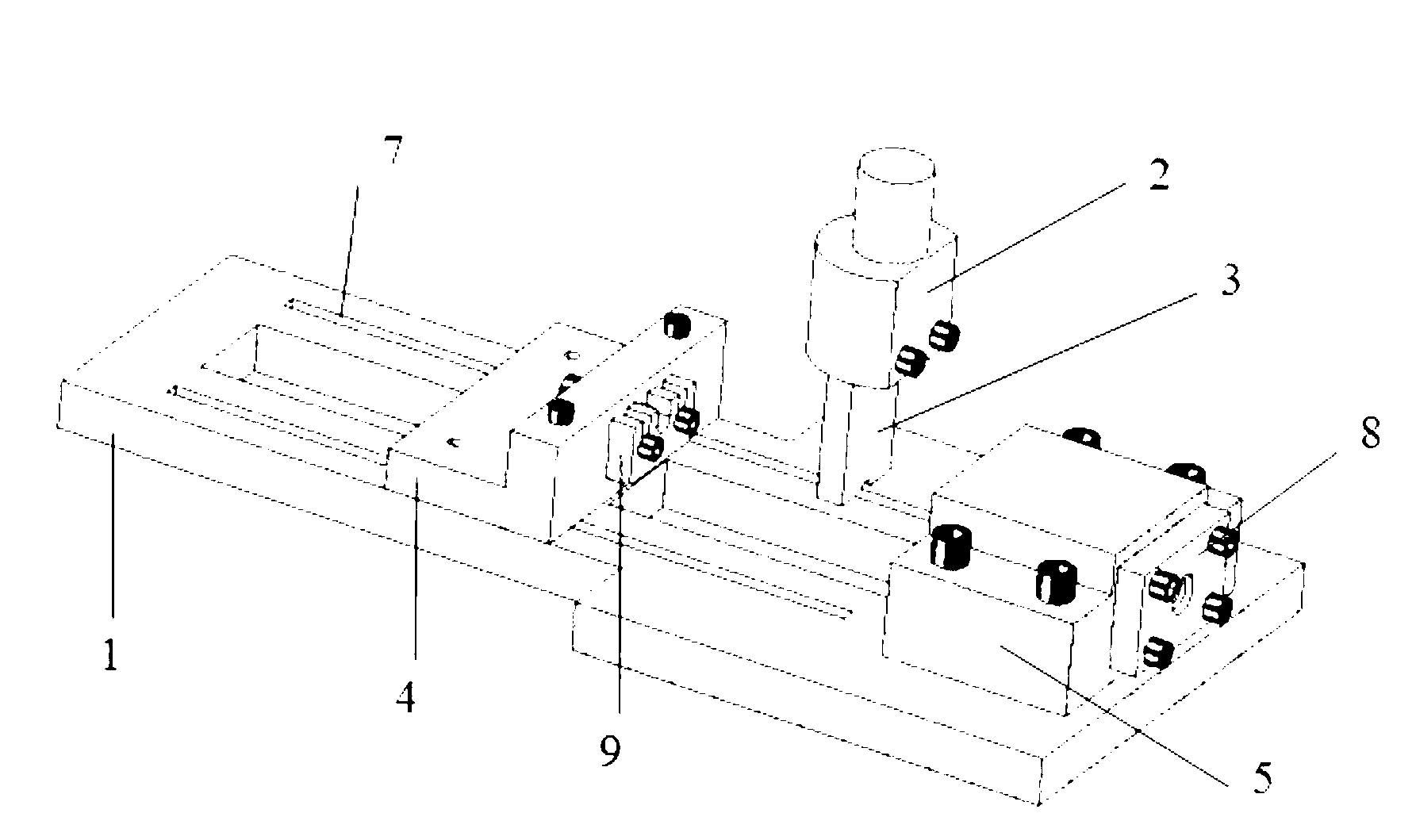
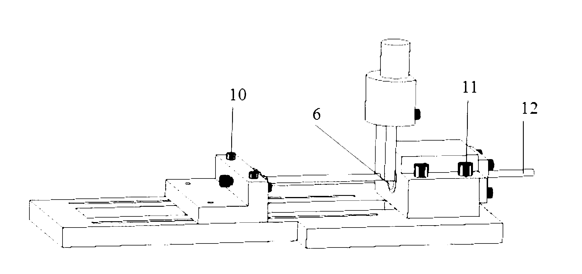
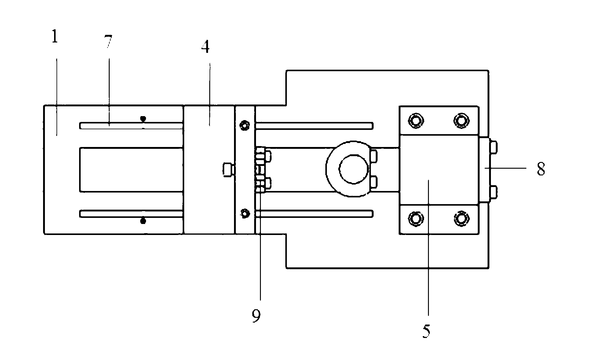
[0020] In this embodiment, it includes a base 1 and an upper mold cavity 2 arranged above the base 1, the base 1 is provided with a guide rail 7, an adjustment seat 4 and a lower mold cavity 5, and the adjustment seat 4 is in contact with the base 1, The lower mold cavity 5 is fixed by the locking bolt 11 and the base 1; the lower mold cavity 5 is fixed on one end of the guide rail 7, and the adjustment seat 4 moves along the guide rail on the other end of the guide rail through the adjustment bolt 10; An inner circle knife 6 is provided, and a knife 3 is arranged in the upper mold cavity 2; a baffle plate 8 with a feeding hole is arranged on the surface of the lower mold cavity 5 opposite to the inner circle knife e...


PUM


Abstract

The invention relates to the technical field of machining, in particular to a material breaking device of a punching machine for round steel workpieces. The material breaking device of the punching machine comprises a base and an upper die cavity arranged above the base, an adjusting seat and a lower die cavity with an inner circular tool are arranged on the base, and the lower die cavity is fixed on the base through locking bolts. A tool is arranged in the upper die cavity. The material breaking device of the punching machine is simple in structure, convenient to operate, high in machining precision, and not prone to causing deformation of workpieces, and when mass processing is carried out, work efficiency can be effectively improved, and labor intensity of workers can be reduced.

Description

technical field [0001] The invention relates to the technical field of mechanical processing, in particular to a punch cutting device for round steel workpieces. Background technique [0002] With the wide use of round steel materials such as cylindrical pins and rotating shafts in aviation, aerospace, defense and other fields, the technical requirements for machining them are getting higher and higher, especially for the positioning length and dimensional consistency of cylindrical pins and rotating shafts , Processing surface smoothness, etc. have special requirements. The existing technology mostly adopts the cutting machine processing method. Although the round steel has a simple structure, due to the influence of rigidity, self-weight, cutting force, cutting heat, clamping force, centrifugal force and other factors, the cutting machine is not only low in processing accuracy, but also prone to Bamboo shape, triangular shape, conical shape, bending and other mechanical d...

Claims


Application Information

Patent Timeline
IPC IPC(8): B21D28/02
Inventor 黄立朝
Owner HUBEI JIANFENG TECH INC
Learn More