Composite materials and methods and apparatus for making same

A technology of equipment and matrix materials, which is applied in the field of composite materials and its manufacturing and equipment, can solve problems such as poor mixing, loss of part precision, inaccurate thickness, etc., achieve high precision and accuracy, reduce replacement costs, and reduce tool wear Effect

Inactive Publication Date: 2013-07-17
TORXX GROUP
View PDF9 Cites 6 Cited by
  • Summary
  • Abstract
  • Description
  • Claims
  • Application Information

AI Technical Summary

Problems solved by technology

This traditional method has three major disadvantages: breakage of the microbeads during mixing, poor mixing at higher volume fractions of microspheres and defect formation
[0024] Disadvantage: Mechanical mixing of beads into matrix material often traps (trapped) gas in the mixture
[0029] b) Imprecise thickness: With traditional bonding materials, when the parts are pressed together, the thickness of the bonding layer is difficult to maintain at an exact optimum thickness over the entire surface area of ​​the mating surfaces, which results in a weaker , and loses precision with respect to the relative position and relative orientation of the components

Method used


Image

  • Composite materials and methods and apparatus for making same
  • Composite materials and methods and apparatus for making same
  • Composite materials and methods and apparatus for making same

Examples


Embodiment Construction

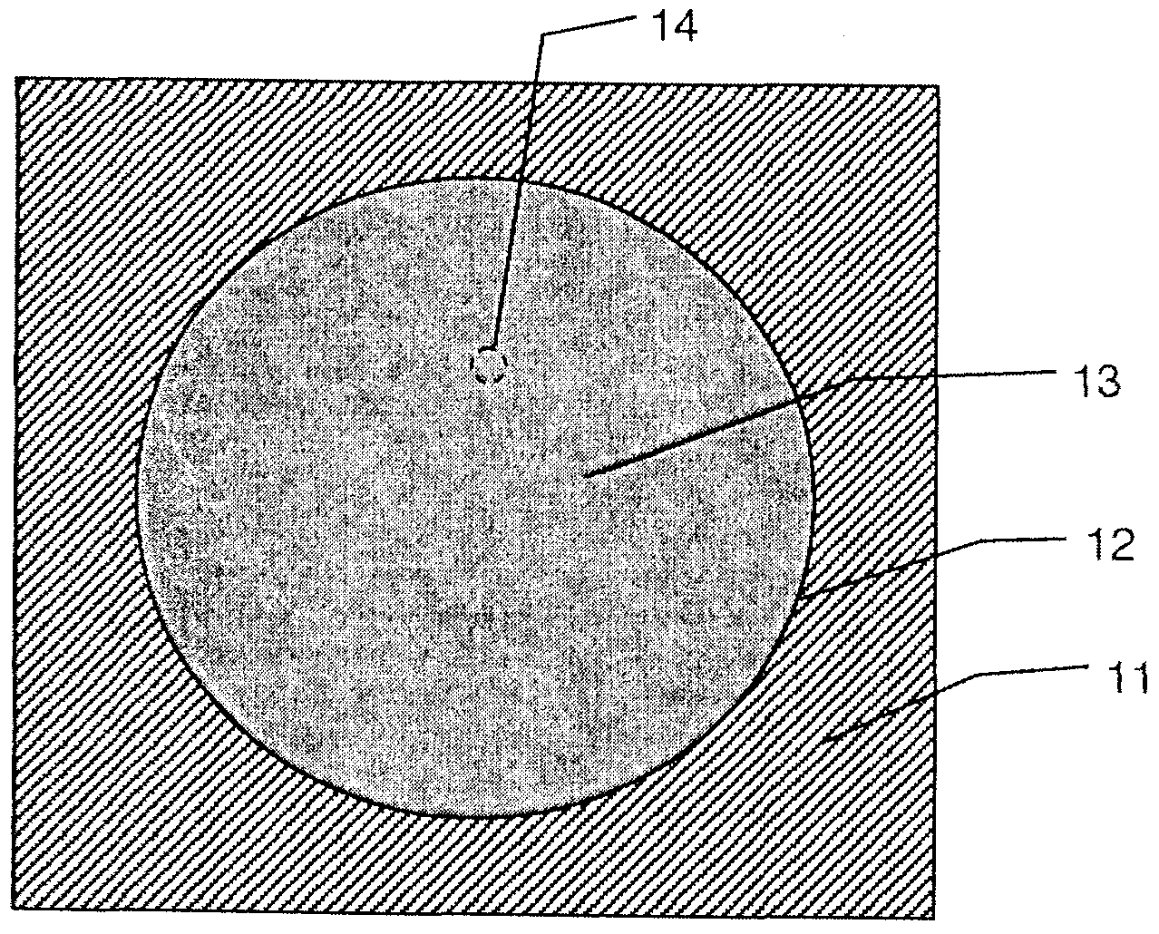
[0061] See originally figure 1 , shows a cross-sectional view of a mold 11 having a mold interior void 12 filled with micro space frame (MSF) material 13 fabricated in accordance with one embodiment of the present invention.

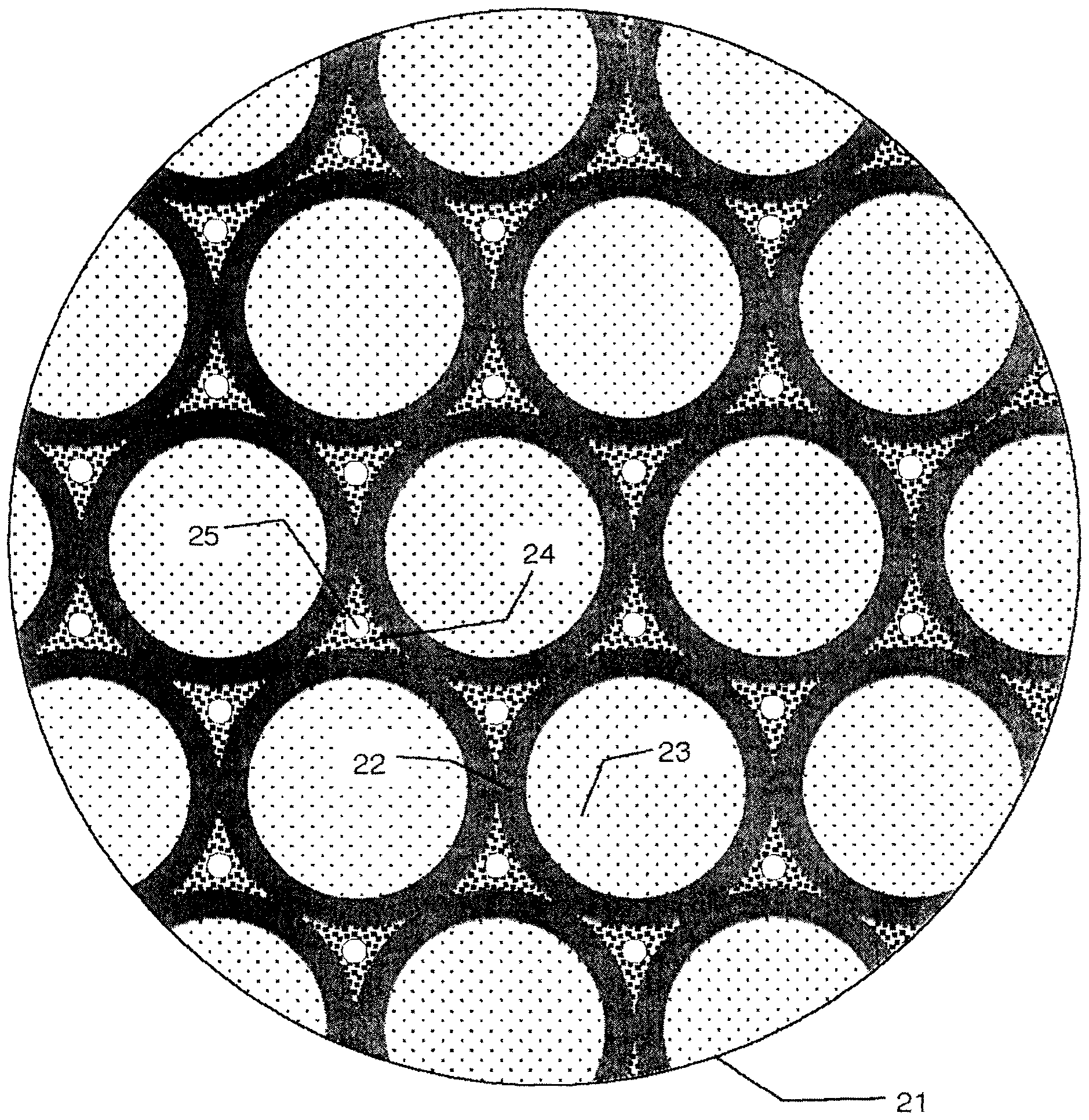
[0062] The composite elements forming the MSF material are generally micro or nano sized, so at the scale visible to the human eye, the micro space frame material 13 appears to be a homogeneous solid. To show the structure of the MSF material, in figure 2 A small circular region 14 of MSF material 13 is shown enlarged in circle 21 .

[0063] Solid Particle Phase:

[0064] exist figure 2 The solid particle phase of MSF material 13, which is composed of many microspheres 16 of equal diameter, is shown in ring 21 of . Microspheres 22 have hollow void spaces 23, but can generally be hollow or solid.

[0065] Each microsphere 22 is shown in mechanical contact with its nearest neighbor. figure 1 Only two-dimensional space is shown in , whereas in three...


PUM

PropertyMeasurementUnit
densityaaaaaaaaaa

Abstract

A composite material comprising a solid particulate material and a matrix material encapsulating the solid particulate material, wherein each dividual particle of the solid particulate material is in contact with at least one adjacent solid particle. A method comprising providing a solid particulate material, providing a mold, evacuating the solid particulate material in the mold to remove gas in the void space between the particles of the particulate material, evaluating the mold, introducing the evacuated solid particulate material into the mold, providing a fluid matrix material, and introducing the fluid matrix material into the void spaces while constraining the solid particulate material.

Description

technical field [0001] The present invention relates to a composite material and its manufacturing method and equipment (device). Background technique [0002] Shaping and forming deformations: [0003] At least some materials and methods currently used for mold components produce dimensionally inaccurate part shapes due to forming deformations. Formation distortion is caused by significant material dimensional changes (typically shrinkage and distortion) that occur during the forming, curing and demolding processes. These dimensional changes may result from: a) temperature changes; b) pressure changes; c) phase changes of the material; d) chemical reactions of the material; and / or e) other material state changes. [0004] To achieve the desired dimensional accuracy, in current practice molded parts are often manufactured dimensionally larger than desired and additional operations such as machining or grinding are used, often time-consuming and expensive processes, to remo...

Claims


Application Information

Patent Timeline
Patent Type & Authority Applications(China)
IPC IPC(8): B22F1/00B01J13/02B22F3/00C04B35/622
CPCB22F3/22B22F2999/00B22F2998/00B28B5/00Y10T428/249921B22F3/02B22F2202/01B22F2303/01B22F2301/05
Inventor 道格拉斯·科伊尔
Owner TORXX GROUP
Why Eureka
Try Eureka