
Local signal to noise ratio-based interferogram filtering method

A technology of interferogram and signal-to-noise ratio, applied in the field of image processing, can solve the problem of unknown noise level and achieve the effect of reducing loss

Active Publication Date: 2013-07-17
CENT FOR EARTH OBSERVATION & DIGITAL EARTH CHINESE ACADEMY OF SCI
View PDF1 Cites 15 Cited by
  • Summary
  • Abstract
  • Description
  • Claims
  • Application Information

AI Technical Summary

Problems solved by technology

However, the noise level in the local window of the interferogram is usually unknown, so how to select an accurate filtering parameter α to improve the adaptability and accuracy of frequency domain filtering is a problem worth studying
This is also the biggest flaw of the current Goldstein frequency domain filtering algorithm.

Method used


Image

  • Local signal to noise ratio-based interferogram filtering method
  • Local signal to noise ratio-based interferogram filtering method
  • Local signal to noise ratio-based interferogram filtering method

Examples


Embodiment Construction

[0020] The technical solutions of the present invention will be described in further detail below with reference to the accompanying drawings and embodiments.

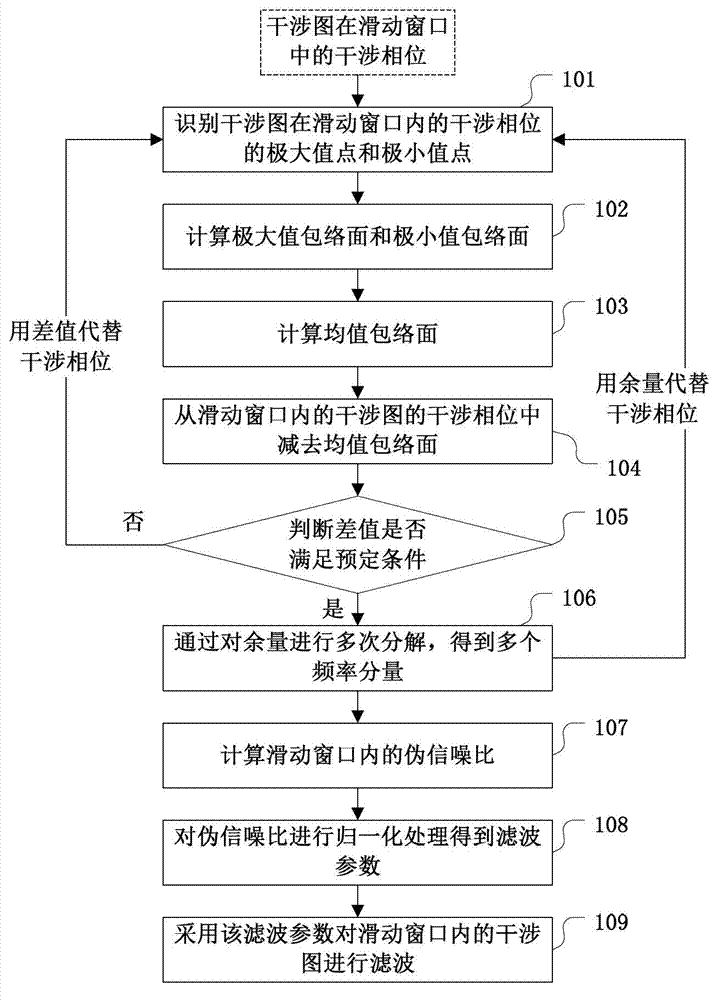
[0021] In view of this problem, the interferogram filtering method of the present invention uses Empirical Mode Decomposition (EMD) technology to decompose the interferometric phase to obtain the local signal-to-noise ratio of the interferogram. The noise level is determined by the local SNR, and then the noise level of the interferogram is adjusted. Targeted filtering.

[0022] For example, according to the method of the present invention, the two-dimensional EMD technology can be used to decompose the interference phase to obtain the components of the phase diagram at different frequency components, wherein the high-frequency component mainly contains the noise information of the original phase, and the low-frequency component contains the original phase. Scale trends. By obtaining the phase components of different ...


PUM


Abstract

The invention relates to a local signal to noise ratio-based interferogram filtering method. According to the method, interferograms in a sliding window are subjected to filtering sequentially by the sliding of the window in the interferograms, wherein a method for performing the filtering on the interferograms in the sliding window comprises the following steps of: decomposing interferometric phases of the interferograms in the sliding window to obtain estimation frequency components of the interferograms in the sliding window; calculating according to the interferometric phases and the estimation frequency components to obtain a local signal to noise ratio of the interferograms in the sliding window; calculating according to the local signal to noise ratio to obtain a filtering parameter; and performing the filtering on the interferograms in the sliding window according to the filtering parameter. By the method, the degree of local noise in the interferograms can be estimated accurately, and the loss of filtering to the phase information of the interferograms is reduced while the noise reduction of the conventional filtering method is provided, so that integral superiority is embodied.

Description

technical field [0001] The invention relates to the field of image processing, in particular to a filtering method of an InSAR interferogram based on a local signal-to-noise ratio. Background technique [0002] Synthetic aperture radar interferometry (Interferometric Synthetic Aperture Radar, INSAR) is based on two SAR images in the same area as the basic data processing, by calculating the phase difference of the two SAR images, the interference image is obtained, and then unwrapped by phase, from A new space-to-earth observation technology for obtaining terrain elevation data in interference fringes. [0003] In the data processing flow of Synthetic Aperture Radar Interferometry (InSAR), filtering the interferogram is a very important step. As mentioned above, the interferogram is used for subsequent phase unwrapping, and the quality of the interferogram will affect the complexity of the subsequent phase unwrapping, which determines the accuracy of the digital elevation m...

Claims


Application Information

Patent Timeline
Patent Type & Authority Applications(China)
IPC IPC(8): G06T5/00G01S13/90
Inventor 刘广宋瑞郭华东
Owner CENT FOR EARTH OBSERVATION & DIGITAL EARTH CHINESE ACADEMY OF SCI
Learn More