Pressure transmitter with waterproof and ventilating membrane

A waterproof gas-permeable membrane and transmitter technology, applied in the direction of measuring fluid pressure, measuring fluid pressure through electromagnetic components, instruments, etc., can solve the problems of damaging circuit boards and sensors, which cannot be fundamentally prevented, and achieve simple processing technology Effect

Active Publication Date: 2013-07-17
ZHUZHOU CSR TIMES ELECTRIC CO LTD +1
View PDF8 Cites 17 Cited by
  • Summary
  • Abstract
  • Description
  • Claims
  • Application Information

AI Technical Summary

Problems solved by technology

[0003] Gauge pressure transmitters generally include a transmitter housing in which circuit boards, sensors, etc. are installed. Both ends of the housing are connected to the tail assembly and the head assembly, and the tail assembly and the head assembly are connected to other equipment. When working, The air pressure inside the transmitter housing should be consistent with the pressure of the surrounding environment, so the inside and outside of the housing should be connected. However, the gas outside the transmitter may contain dust, water, oil and other particulate impurities. These impurities will enter the housing. Damage the circuit boards, sensors, etc. in the housing. The current waterproof, dustproof, and oil-proof measures are mainly to improve the environment where the pressure transmitter is located, and to remove dust and dry the surrounding environment. Such measures cannot fundamentally prevent impurities into the pressure transmitter housing, so it is necessary to design a new type of pressure transmitter that can completely block impurities from entering

Method used


Image

  • Pressure transmitter with waterproof and ventilating membrane
  • Pressure transmitter with waterproof and ventilating membrane
  • Pressure transmitter with waterproof and ventilating membrane

Examples


Embodiment Construction

[0016] The present invention will be further described below in conjunction with drawings and embodiments.

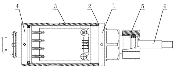
[0017] Such as figure 1 The shown pressure transmitter with a waterproof and gas-permeable membrane is assembled from a tail assembly 4, a housing 3, and a head assembly 1. A circuit board, a sensing core, etc. are arranged in the housing 3, and the head assembly 1 is screwed to the At one end of the housing 3, the device is sealed by an O-ring 2, and the other end of the head assembly is connected with the air pipe joint 6 by means of the joint nut 5.

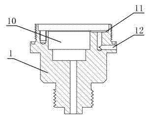
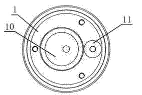
[0018] The structure of head component 1 is as follows figure 2 , image 3 As shown, a cavity 10 is arranged in the end surface of the head assembly located in the housing 3, the pipeline in the head assembly communicates with the bottom of the cavity 10, the air pipe joint 6 is connected behind the head assembly, and the transmission in the housing 3 Components such as the sensing core can also be accommodated in t...


PUM


Abstract

The invention discloses a pressure transmitter with a waterproof and ventilating membrane. A circuit board of the transmitter, a sensing core body and the like are arranged in a casing, the front end and the rear end of the casing are connected with a tail assembly and a head assembly, an eccentric cavity is arranged in the end face of the head assembly in the casing, a pipeline in the head assembly is communicated with the bottom of the cavity, the outer part of the head assembly is connected with an air hose connector, an L-shaped ventilating hole is arranged in the head assembly, one end of the ventilating hole is arranged on the lateral wall of the head assembly, the other end of the ventilating hole is arranged on the end face of the head assembly in the casing, a groove is arranged on the periphery of the opening of the ventilating hole, the opening is arranged at the bottom of the groove, a pressing sheet is fixed in the groove, the waterproof and ventilating membrane is fixed on a central hole portion of the pressing sheet, air inside and outside can pass through the L-shaped ventilating hole and the waterproof and ventilating membrane, and impurities of dust, water, oil and the like can be blocked.

Description

technical field [0001] The invention relates to a pressure transmitter. Background technique [0002] The pressure transmitter is to convert the physical pressure parameters such as gas and liquid felt by the pressure measuring element sensor into a standard electrical signal, so as to supply secondary instruments such as indicating alarms, recorders, regulators, etc. for measurement, indication and process adjustment. The general pressure transmitter is mainly composed of three parts: the load cell sensor, the measurement circuit and the process connection. [0003] Gauge pressure transmitters generally include a transmitter housing in which circuit boards, sensors, etc. are installed. Both ends of the housing are connected to the tail assembly and the head assembly, and the tail assembly and the head assembly are connected to other equipment. When working, The air pressure inside the transmitter housing should be consistent with the pressure of the surrounding environment...

Claims


Application Information

Patent Timeline
Patent Type & Authority Applications(China)
IPC IPC(8): G01L9/00G01L19/06
Inventor 张燕亮王建飞刘忠柏
Owner ZHUZHOU CSR TIMES ELECTRIC CO LTD
Why Eureka
Try Eureka