Expansion valve and shockproof spring
A technology of anti-shock spring and expansion valve, which is applied in the field of expansion valve, can solve the problems of insensitive response of the valve core, vibration of the valve core, noise, etc., and achieve the effect of low cost
- Summary
- Abstract
- Description
- Claims
- Application Information
AI Technical Summary
Problems solved by technology
Method used
Image

Examples
no. 1 Embodiment approach ]
[0034] In this embodiment, the expansion valve of the present invention is embodied as a thermostatic expansion valve suitable for a refrigeration cycle of an automobile air conditioner. Although the refrigeration cycle is equipped with a compressor for compressing the refrigerant in the cycle, a condenser for condensing the compressed refrigerant, a liquid receiver for separating the condensed refrigerant into gas and liquid, and throttling and expanding the separated liquid refrigerant into a mist and an expansion valve that sends out the mist refrigerant, and an evaporator that cools the air in the vehicle compartment by evaporating the latent heat of evaporation, and the detailed description of the configurations other than the expansion valve is omitted.
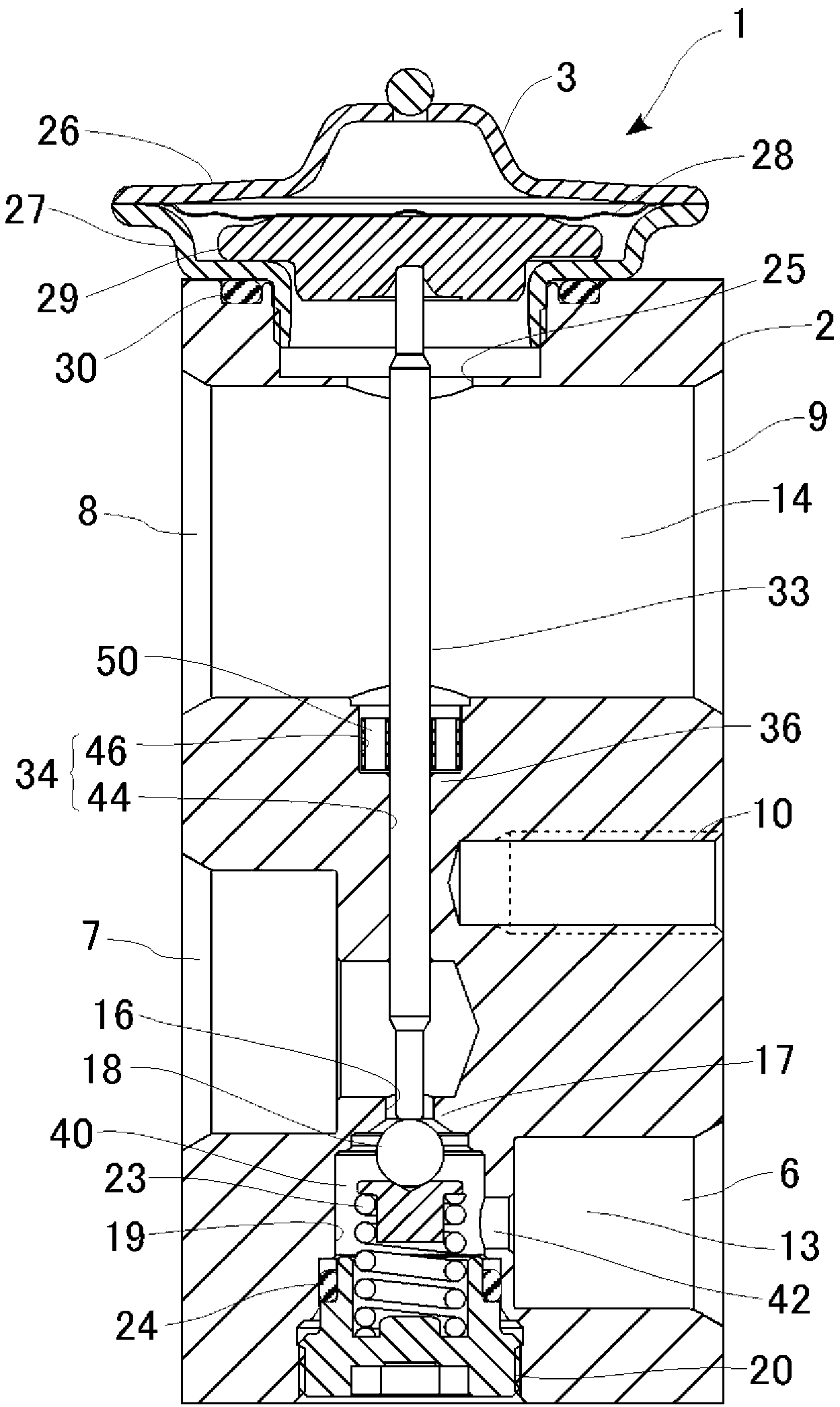
[0035] figure 1 It is a cross-sectional view of the expansion valve of the embodiment.
[0036] The expansion valve 1 has a main body 2 formed by subjecting a member obtained by extruding a raw material made of alumin...
Deformed example 1
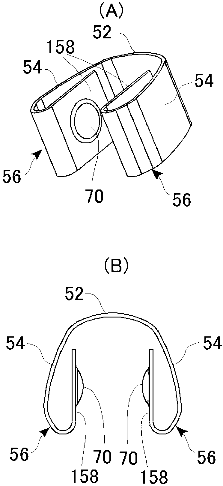
[0053] image 3 It is a figure which shows the structure of the antivibration spring of the modification of 1st Embodiment. (A) is a perspective view showing the overall structure of the anti-vibration spring. (B) is a plan view showing a state where the anti-vibration spring is inserted into the stepped hole. However, the illustration of the stepped hole and the shaft is omitted.
[0054] In this modified example, a hemispherical protruding portion 70 is provided at the center of the inner surfaces (directly facing surfaces) of the pair of inner spring portions 158 . When the anti-vibration spring of this modified example is inserted into the large-diameter portion 46 , the pair of protrusions 70 come into point contact with the shaft 33 . With such a configuration, even if the shaft 33 is slightly inclined, the point contact state between the protrusion 70 and the shaft 33 can always be ensured, and the flexible support state of the anti-vibration spring is maintained. I...
Deformed example 2
[0056] Figure 4 It is a figure which shows the structure of the anti-vibration spring of another modification of 1st Embodiment. (A) is a perspective view showing the overall structure of the anti-vibration spring. (B) is a plan view showing a state where the anti-vibration spring is inserted into the stepped hole.
[0057] In this modified example, a claw portion 72 (corresponding to a “locking portion”) is formed at an edge of a portion of the anti-vibration spring that is in contact with the large-diameter portion 46 . That is, the claw portion 72 is formed by partially cutting out the upper end edges of the pair of rolled portions 156 and bending them outward. With such a configuration, when the anti-vibration spring is inserted into the large-diameter portion 46, the claw portion 72 is shaped to be caught on the inner wall of the large-diameter portion 46, thereby preventing the anti-vibration spring from falling off. In addition, in this modified example, although th...
PUM
 Abstract
Description
Claims
Application Information
 - R&D
- Intellectual Property
- Life Sciences
- Materials
- Tech Scout
- Unparalleled Data Quality
- Higher Quality Content
- 60% Fewer Hallucinations
Browse by: Latest US Patents, China's latest patents, Technical Efficacy Thesaurus, Application Domain, Technology Topic, Popular Technical Reports.
© 2025 PatSnap. All rights reserved.Legal|Privacy policy|Modern Slavery Act Transparency Statement|Sitemap|About US| Contact US: help@patsnap.com