Apparatus for machining, particularly for cutting a tubular or round section body

A technology of mechanical processing and equipment, applied in metal processing equipment, sawing equipment, metal sawing equipment, etc., can solve the problems of difficult operation, expensive, large equipment, etc.

Inactive Publication Date: 2013-07-10
精密工具有限公司
View PDF6 Cites 5 Cited by
  • Summary
  • Abstract
  • Description
  • Claims
  • Application Information

AI Technical Summary

Problems solved by technology

This necessarily requires that the frame of the clamping mechanism must have a length slightly in excess of 1000mm when machining a part of, say, 1000mm diameter, so that the device becomes rather bulky and heavy, thus difficult to handle and often dangerous because the device does not Again suitable for stable manual operation
In fact, there are already options in the prior art to use multiple sizes of equipment for parts of different diameters, which is of course expensive since it requires at least two or three different sizes of equipment parts
[0006] On the other hand, when machining thin-walled parts, such as thin-walled spiral welded pipes, the clamping mechanism tightened around the part may compress the part, changing its shape, thus making it difficult to produce straight cut results , or even impossible
[0007] Furthermore, adjusting the machining or cutting depth to an optimum is a difficult operation in prior art equipment

Method used


Image

  • Apparatus for machining, particularly for cutting a tubular or round section body
  • Apparatus for machining, particularly for cutting a tubular or round section body
  • Apparatus for machining, particularly for cutting a tubular or round section body

Examples


Embodiment Construction

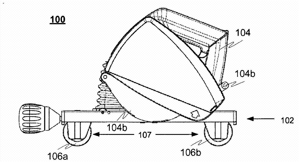
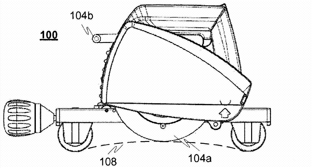
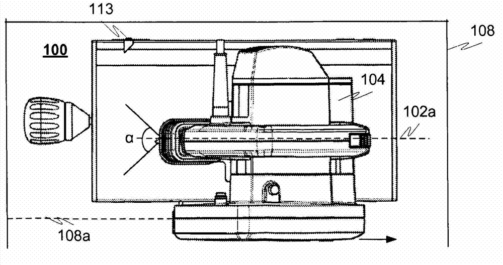
[0029] figure 1 and 5 shows an example device 100 in a transport state, wherein the tool part 104a is covered by a pivotable protective cover 104b, and figure 2 The apparatus 100 is shown in an operative condition, wherein the pivotable guard 104b is rotated such that at least a portion of the tool part 104a is exposed outside the guard 104 . The device 100 comprises a frame element 102 and a machining unit 104 for rotating a tool part 104a. Additionally, the example apparatus includes at least one first support element 106a and at least one second support element 106b for supporting the apparatus 100 on a workpiece 108 while the workpiece is being machined. The apparatus is also provided with adjustment elements, such as hinges or slide rails, for moving the tool part 104 a towards or away from the workpiece 108 relative to the frame element 102 . Thus, for example, during the process of cutting and / or beveling the part 108, the tool part 104a is moved toward the workpiece ...


PUM


Abstract

An apparatus (100) for machining a tubular or round-bar type piece, wherein the apparatus comprises a frame element (102), a machining unit (104), as well as a threaded shaft (110), which is fitted to the frame element in a rotatable and axially immobile fashion and has a first section 110a) provided with a right-handed thread and a second section (110b) with a left-handed thread. The first section is provided with at least one first support element (106a) and the second section is provided with at least one second support element (106b), the mutual distance between the support elements being adjustable in response to rotating the threaded shaft, such that the support elements, for example wheels, are adapted to touch a workpiece and to support and guide the apparatus (100) in the process of machining the piece. At least one of the support elements, such as wheels (106a, 106b), is adapted to be capable of rotating relative to its axis in response to moving the apparatus along the surface of a workpiece.

Description

technical field [0001] The invention relates to a device for machining (in particular for cutting, but also scoring and / or bevelling) tubular or round rod type parts. Background technique [0002] Various tools are known from the prior art for machining (for example for cutting or milling) tubular or round bar type parts, or beveling the part at its end. One example tool of the prior art is an angle grinder, which includes a rotating disc for cutting parts. The rotary disc can also be used to bevel the ends of parts. [0003] However, the problem with these tools is, for example, how to produce a straight cutting result across the entire pipe, i.e. how to make the end point exactly coincide with the start point as the cutting tool advances along the pipe surface, without the operator having to perform any corrective actions, e.g. very close to the end (thus creating a bend in the cut line). Another problem with the existing known devices is that there are no supports, mak...

Claims


Application Information

Patent Timeline
Patent Type & Authority Applications(China)
IPC IPC(8): B21D37/04B23D21/06B23D21/04B23D45/12
CPCB23C1/20B23C3/34B23D45/126B23Q9/0021B23Q9/0028B27B9/02Y10T29/5199Y10T409/304144Y10T409/30644Y10T83/0333Y10T83/667Y10T83/68B21D37/04B23D21/04B23D21/06B23D45/12B23D47/04B23C3/122B23C3/126B23Q9/0035
Inventor S·马科宁M·普里哈
Owner 精密工具有限公司
Why Eureka
Try Eureka