
Expressway programmable logic controller (PLC) tunnel monitoring system

A technology of expressway and monitoring system, applied in the direction of electrical program control, comprehensive factory control, etc., which can solve the problems that the tunnel monitoring system does not propose strategy control, long lines of super-large tunnels, long system loading time, etc.

Inactive Publication Date: 2013-07-10
KUNMING UNIONSCIENCE TECH CO LTD
View PDF6 Cites 9 Cited by
  • Summary
  • Abstract
  • Description
  • Claims
  • Application Information

AI Technical Summary

Problems solved by technology

[0005] The present invention designs a highway PLC tunnel monitoring system, which solves the technical problems as follows: (1) The existing system has long loading time and unresponsive interface caused by the long line of super-large tunnels, many equipments, and large amount of data collection (2) The current tunnel monitoring system does not propose strategic control, and the system cannot automatically or manually control the equipment when the environment and time factors change; (3) The existing tunnel monitoring system does not adopt data layering structure

Method used


Image

  • Expressway programmable logic controller (PLC) tunnel monitoring system
  • Expressway programmable logic controller (PLC) tunnel monitoring system
  • Expressway programmable logic controller (PLC) tunnel monitoring system

Examples


Embodiment Construction

[0025] Combine below Figure 1 to Figure 5 , the present invention is further described:

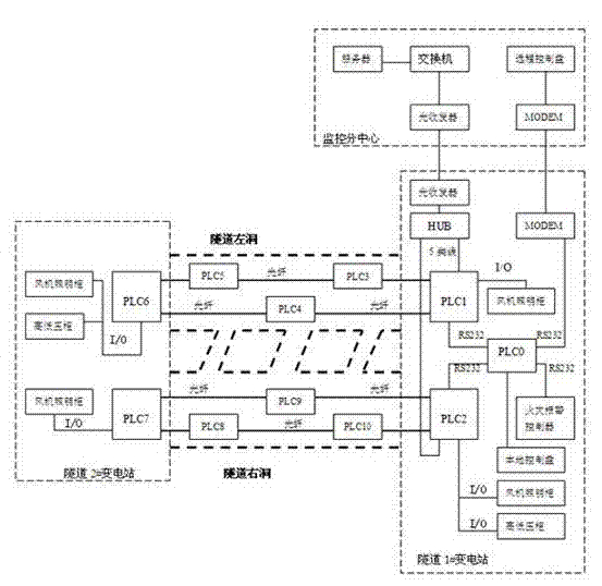
[0026] Such as figure 1 As shown, the PLC system of each tunnel forms a fiber optic ContorllerLink redundant token ring network at the left hole and the right hole of the tunnel respectively, and the two fiber optic ContorllerLink redundant token ring networks are independent control systems that do not interfere with each other. . The PLC installed in the monitoring equipment room is connected to the main control PLC through HostLink, and exchanges data with the server of the tunnel monitoring sub-center through Ethernet module, HUB, and optical fiber transceiver. The main control PLC is connected to a local touch screen in the monitoring room, and is connected to a remote touch screen of the monitoring sub-center through a MODEM.

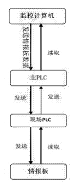
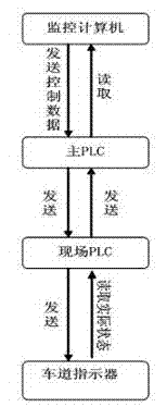
[0027] Such as figure 2 As shown: Among them, the variable information board control unit is mainly responsible for sending the information written by ...


PUM


Abstract

The invention relates to an expressway programmable logic controller (PLC) tunnel monitoring system which comprises a variable message sign, a lane indicator, illumination equipment, a fan, a master PLC and a plurality of site PLCs. An expressway tunnel left cave and an expressway tunnel right cave are respectively provided with an optical fiber redundancy token looped network. Two optical fiber redundancy token looped networks are independent of each other. The variable message sign, the lane indicator, the illumination equipment and the fan are respectively connected with a site PLC. Each site PLC is connected with a monitoring computer in a signal mode through the master PLC. The master PLC and the plurality of site PLCs are connected in the optical fiber redundancy token looped networks. According to the expressway PLC tunnel monitoring system, an integrated scheme which combines a tunnel PLC and a central control computer is adopted in an expressway tunnel swarm intelligence automatic system, decentralized control and centralized management are carried out on electromechanical devices of an expressway tunnel, meanwhile, monitoring is carried out on the internal environment of a cave of the expressway tunnel, the external environment of the cave of the expressway tunnel and the electromechanical devices, not only are control requirements of the expressway tunnel to traffic, illumination and ventilation inside the cave of the expressway tunnel satisfied, but also the purposes of coordination of comprehensive monitoring on the whole expressway PLC tunnel monitoring system and energy saving are achieved.

Description

technical field [0001] The invention relates to a monitoring system, in particular to a PLC tunnel monitoring system for expressways. Background technique [0002] In recent years, with the rapid development of my country's highway transportation industry, the grade of highways has been continuously improved, and the mileage of traffic has been increasing year by year. Highway construction has become a pillar industry that stimulates the growth of the national economy. Control management has become an important issue in the safe and normal operation of highway tunnels. [0003] The tunnel monitoring system has the characteristics of harsh monitoring environment, scattered control points, and a lot of analog and digital information. At the same time, with the rapid development of computers, network communications, electronic technology and intelligent transportation systems (ITS), programmable logic controllers (PLCs) ) (Programmable controller of tunnel) is more and more wid...

Claims


Application Information

Patent Timeline
IPC IPC(8): G05B19/418
Inventor 邵宗凯吴建德王晓东
Owner KUNMING UNIONSCIENCE TECH CO LTD
Learn More