
Extra-large imaging depth three-dimensional display method based on optical 4f system

A three-dimensional display and optical technology, applied in optics, optical components, instruments, etc., can solve the problems of small depth of three-dimensional image imaging, easy fatigue and fatigue after long-term viewing, and achieve easy implementation and overcome the inability to apply monocular helmet display. , The effect of the system is simple

Inactive Publication Date: 2013-07-10
NANKAI UNIV
View PDF6 Cites 14 Cited by
  • Summary
  • Abstract
  • Description
  • Claims
  • Application Information

AI Technical Summary

Problems solved by technology

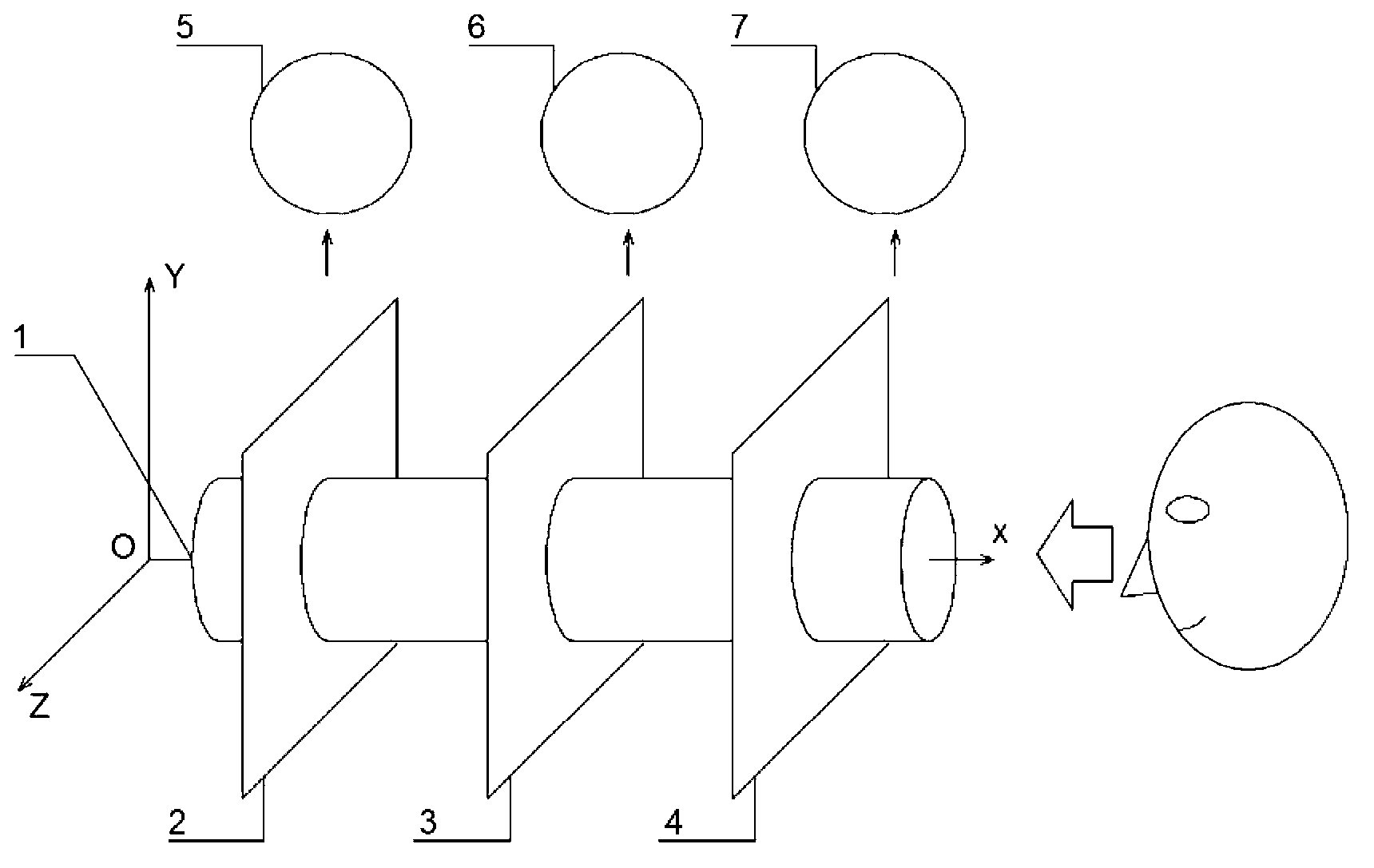
[0003] The purpose of the present invention is to solve the problem that the three-dimensional image formed by the existing technology has a small imaging depth and is prone to fatigue after long-term viewing, and provides a three-dimensional display method with a super large imaging depth based on the optical 4f system
[0004] Aiming at the problems existing in the existing 3D helmet 3D display system based on the binocular parallax method, the present invention provides a new method for 3D helmet display based on the ultra-large imaging depth of the optical 4f imaging system
Compared with the existing binocular parallax-based method, this method can obtain greater imaging depth, overcome the problem of fatigue when watching for a long time, and can be used in both monocular and binocular helmet display systems

Method used


Image

  • Extra-large imaging depth three-dimensional display method based on optical 4f system
  • Extra-large imaging depth three-dimensional display method based on optical 4f system
  • Extra-large imaging depth three-dimensional display method based on optical 4f system

Examples


Embodiment

[0033] 1. Divide the 3D image to be displayed into a series of 2D images

[0034] Input the three-dimensional image to be displayed into the computer to form a numerical three-dimensional model through computer modeling method, according to the number of display layers m of the display system (m=3 in this embodiment) and the display depth position s i (i=1,...m), (in this embodiment, the display depth from the reference plane is s 1 =0.1m, s 2 =0.5m and s 3 =1m), slice the 3D model to obtain m slices with depths of s i 2D image of (i=1,...m);

[0035] 2. Generate coded images

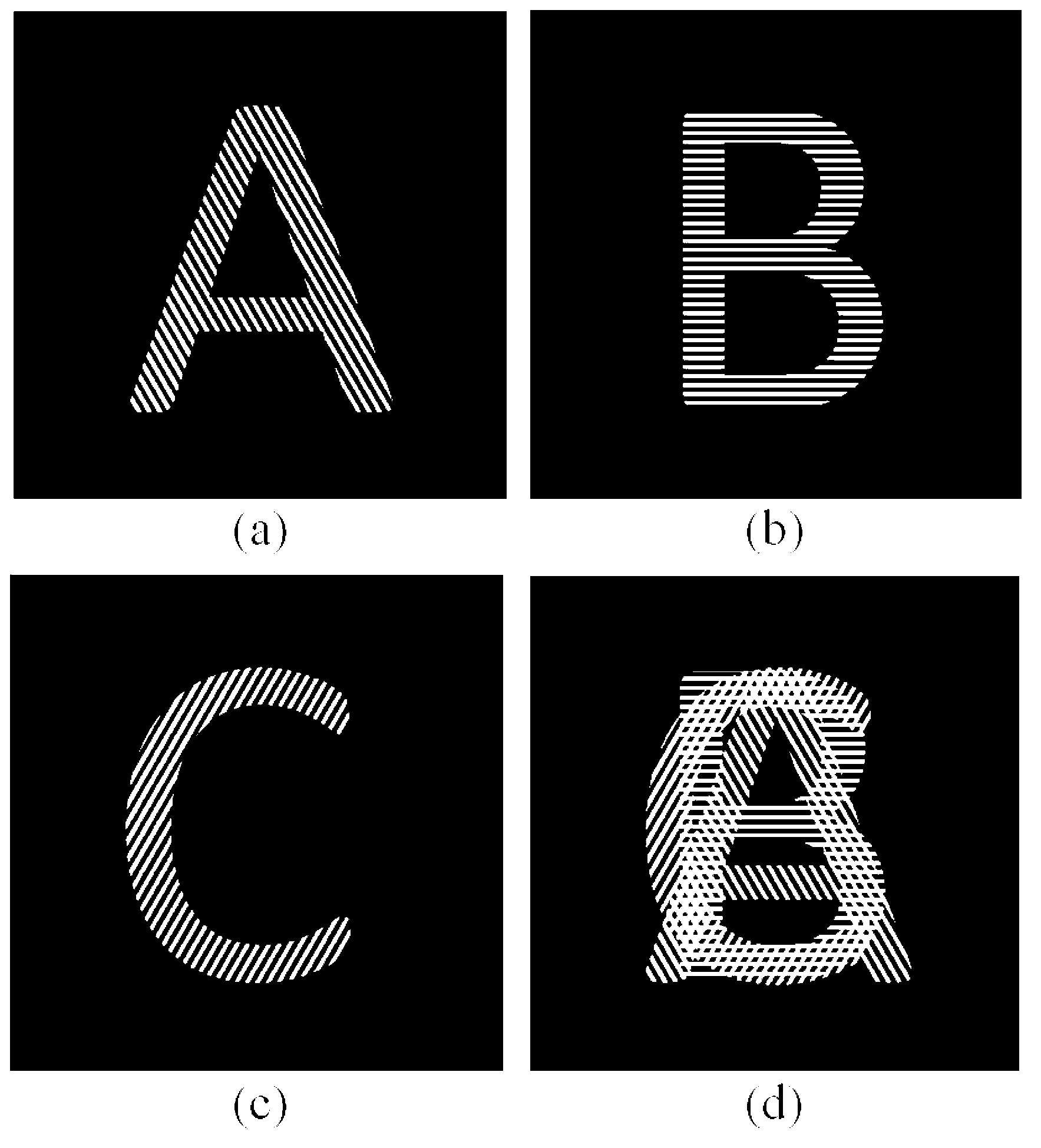
[0036] According to the number of display layers and the distance between the designed first-level spectrum and the center of the spectrum is d (d=5mm in this embodiment), a corresponding number of fringe images at different angles are designed, and the interval a of the fringes can be expressed as: (a=52 microns in this embodiment), where λ is the wavelength of the incident light (the wavelength ...


PUM


Abstract

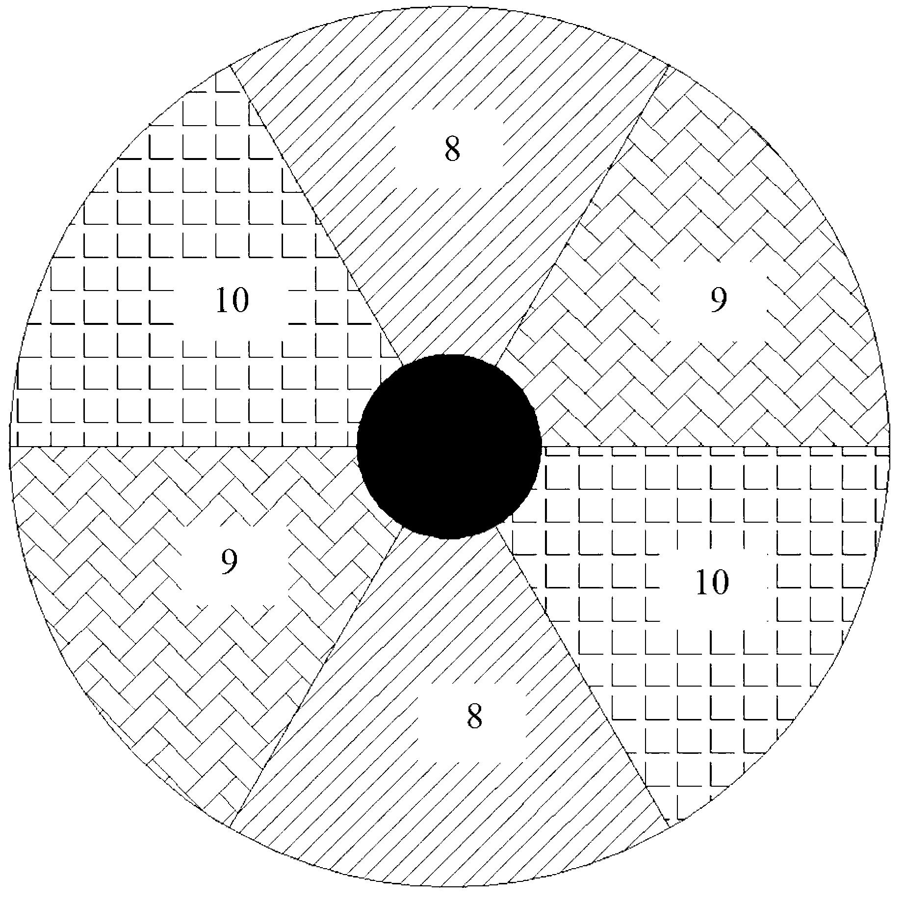
The invention discloses an extra-large imaging depth three-dimensional display method based on an optical 4f system, belongs to the technical field of helmet-based three-dimensional display and mainly solves the problems that the three-dimensional display image has small depth and cannot be displayed in a monocular helmet in a three-dimensional mode and people are easily fatigue after watching the image for a long time. The method comprises the following steps: segmenting a three-dimensional image to be displayed into a series of two-dimensional images with different imaging depths, respectively modulating the two-dimensional images with different imaging depths by employing stripe images in different directions to acquire a coded image; putting the coded image on an input panel of the optical 4f system, putting a phase template on the spectrum surface, wherein the phase template is formed by splicing a series of lenses with different focal distances, redisplaying the coded two-dimensional images at the imaging positions of different corresponding depths on the output panel of the optical 4f system, and realizing extra-large imaging depth three-dimensional display.

Description

technical field [0001] The invention belongs to the technical field of three-dimensional display based on a helmet, and mainly solves the problems that the three-dimensional display has a small depth of field, is prone to fatigue after watching for a long time, and cannot be applied to the three-dimensional display of a monocular helmet. Background technique [0002] The method of using retinal projection imaging is a common helmet-assisted display technology. Through the optical projection display device, the formed two-dimensional image is projected on a fixed image plane position to form a virtual display. In order to realize the viewing of three-dimensional images, it is necessary to convert the virtual two-dimensional images projected on the retina into three-dimensional images. The existing method that can be used for reference is the stereoscopic display technology based on binocular parallax, but the three-dimensional images formed by this technology exist The imagin...

Claims


Application Information

Patent Timeline
IPC IPC(8): G02B27/22G02B27/01
Inventor 杨勇袁小聪许波张珊周奥杨初蕾申诗倩
Owner NANKAI UNIV
Learn More