
Synthetic aperture radar (SAR) imaging method based on field programmable gate array (FPGA)

An imaging method and azimuth technology, applied in the design of radar real-time signal processing system and remote sensing, missile, and digital signal processing fields, can solve the SAR system's limited environmental space and heat dissipation conditions, high system space and heat dissipation conditions, and insufficient resource utilization. and other problems, to achieve the effect of fast operation speed, improved signal processing speed, and fast processing speed

Active Publication Date: 2013-07-10
XIDIAN UNIV
View PDF1 Cites 27 Cited by
  • Summary
  • Abstract
  • Description
  • Claims
  • Application Information

AI Technical Summary

Problems solved by technology

In this form, although DSP has the ability to complete complex operations, it is implemented based on seriality, its parallelism is low, resource utilization is insufficient, and the operation speed is slow.
Moreover, the complex multi-board form of FPGA+DSP has high requirements on system space and heat dissipation conditions, while the environmental space and heat dissipation conditions of the missile-borne SAR system are limited, which cannot meet the requirements of FPGA+DSP multi-board card imaging platform

Method used


Image

  • Synthetic aperture radar (SAR) imaging method based on field programmable gate array (FPGA)
  • Synthetic aperture radar (SAR) imaging method based on field programmable gate array (FPGA)

Examples


Embodiment Construction

[0020] specific implementation

[0021] The present invention will be further described below in conjunction with the accompanying drawings.

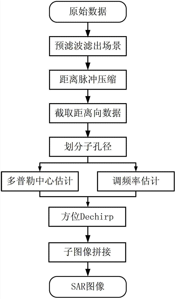
[0022] refer to figure 1 , the specific implementation steps of the present invention are as follows:

[0023] Step 1. Range Pulse Compression

[0024] 1.1) Windowing processing: I and Q two-way data are the real and imaginary parts of the radar echo data, and the multiplication IP cores inside the two FPGAs are called to multiply the I and Q two-way data of the radar echo data by the window function. Among them, the window function is a 16384-point hamming window generated by Matlab software, which is normalized and quantized into a 9-bit signed number and stored in the ROM of the FPGA; the I and Q data are the echo data collected by the radar AD. Both are 12bit, the front end is spliced ​​into 16bit data after zero padding, and the output result of the multiplier is 25bit. Since the subsequent FFT requires the number of data bits t...


PUM


Abstract

The invention discloses a synthetic aperture radar (SAR) imaging method based on field programmable gate array (FPGA). The SAR imaging method based on the FPGA mainly solves the problems that an existing system is complex in structure and slow in data processing speed. The SAR imaging method based on the FPGA comprises the following steps: calling a multiplying unit in the FPGA, conducting fast Fourier transform (FFT) operation after multiplying each array of distance direction data and hamming window data after quantification, finishing distance pulse pressure; calculating a scene central location of the distance direction by inertia parameters, intercepting the distance direction data; transposing acquired data by interception, realizing to store aperture data based on direction; estimating a Doppler central value and a Doppler frequency modulation rate based on inertia navigation parameters; constructing a Doppler frequency shift function, a Doppler frequency modulation function and a direction hamming window function based on the estimated Doppler central value and the Doppler frequency modulation rate; conducting FFT operation by multiplying each array of the direction data after finishing the distance impulse pressure with the Doppler frequency shift function, the Doppler frequency modulation function and the direction hamming window function, and acquiring final imaging data. The SAR imaging method based on the FPGA has the advantages of simplifying an SAR imaging system structure, improving processing speed, and capable of being used in the SAR imaging under a missile-borne module.

Description

technical field [0001] The invention belongs to the technical field of digital signal processing, relates to a radar imaging method, and can be applied to the design of radar real-time signal processing systems, remote sensing, missiles and other fields. Background technique [0002] Synthetic Aperture Radar (SAR) has high resolution in two-dimensional range and azimuth, and can perform high-resolution two-dimensional imaging of the scene. It can detect and locate targets all-weather, all-day, and long-distance, and plays an important role in military and many civilian fields. Common SAR imaging algorithms include range-Doppler R-D algorithm, line frequency modulation scaling CS algorithm and so on. Range-Doppler imaging algorithm, as a main algorithm of synthetic aperture radar imaging, plays an important role in the field of synthetic aperture radar imaging. [0003] At present, the commonly used radar imaging platform mostly adopts the form of FPGA+DSP. Taking advantage...

Claims


Application Information

Patent Timeline
IPC IPC(8): G01S13/90
Inventor 全英汇陈露露邢孟道李亚超李艳红何振
Owner XIDIAN UNIV
Learn More