Measurement turntable for bidirectional reflection distribution function of sample
A two-way reflection distribution and turntable technology, which is applied in the measurement of scattering characteristics, etc., can solve the problems of high cost and large volume of BRDF measurement turntable, and achieve the effect of low price, moderate size and simple mechanical structure
- Summary
- Abstract
- Description
- Claims
- Application Information
AI Technical Summary
Problems solved by technology
Method used
Image

Examples
specific Embodiment approach 1
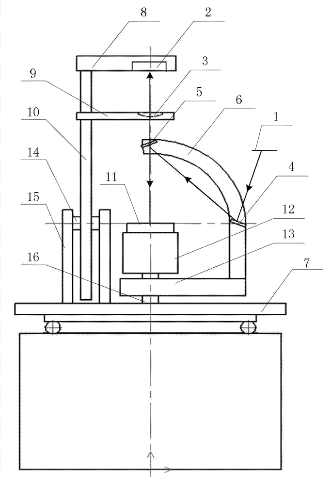
[0044] Specific implementation mode one: the following combination figure 1 Describe this embodiment, the sample bidirectional reflectance distribution function measurement turntable described in this embodiment, it includes laser 1, it also includes detector 2, field lens 3, first plane reflector 4, second plane reflector 5, light source Bracket 6, horizontal turntable 7, detector mounting frame 8, field mirror mounting frame 9, connecting rod 10, sample 11, sample seat 12, base 13, first rotating shaft 14, two end plates 15 and second rotating shaft 16 ,
[0045] The detector mounting frame 8 and the field lens mounting frame 9 are arranged on the upper end of the connecting rod 10 from top to bottom, and the connecting rod 10 is vertically connected with the first rotating shaft 14 through a coupling, and the first rotating shaft 14 is arranged between the two end plates 15 Between, the bottom ends of the two end plates 15 are fixed on the horizontal turntable 7; the detec...
specific Embodiment approach 2
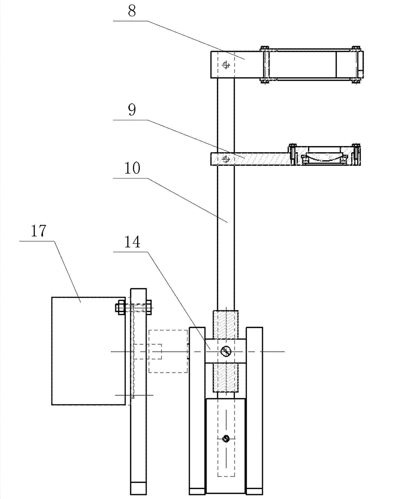
[0048] Specific implementation mode two: the following combination figure 2 Describe this embodiment, this embodiment is a further description of Embodiment 1, this embodiment also includes a first three-phase stepper motor 17,
[0049] The output shaft of the first three-phase stepping motor 17 is connected with the first rotating shaft 14 through a thin plate coupling, and the first three-phase stepping motor 17 is used to drive the first rotating shaft 14 to rotate, so that the detector 2 is in the direction of the zenith angle. on sports.
[0050] In order to realize the movement of the detector 2 in the direction of the zenith angle, the detector 2 is fixed in the detector mounting frame 8, and the detector mounting frame 8 and the field lens mounting frame 9 are placed together on the connecting rod 10, and the connecting rod 10 passes through The detector shaft coupling is connected with the first rotating shaft 14, and the first three-phase stepper motor 17 is also c...
specific Embodiment approach 3
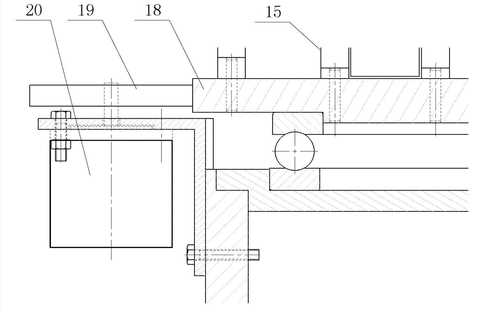
[0052] Specific implementation mode three: the following combination image 3Describe this embodiment, this embodiment is the further explanation to embodiment one or two, this embodiment also includes driven gear 18, driving gear 19 and two-phase stepper motor 20, and the diameter of driven gear 18 is larger than driving gear 19 diameter of;
[0053] The driven gear 18 is socketed on the outer circular surface of the horizontal turntable 7, the driven gear 18 cooperates with the driving gear 19, and the driving gear 19 is socketed on the output shaft of the two-phase stepping motor 20, and the two-phase stepping motor 20 is used To drive the driving gear 19 to rotate, thereby driving the horizontal turntable 7 to rotate in the horizontal direction, so as to realize the change of the azimuth angle of the detector 2 .
[0054] The entire device for the zenith angle movement of the detector 2 is placed on the horizontal turntable 7. Due to the large moment of inertia, the drive...
PUM
 Abstract
Description
Claims
Application Information
 - R&D
- Intellectual Property
- Life Sciences
- Materials
- Tech Scout
- Unparalleled Data Quality
- Higher Quality Content
- 60% Fewer Hallucinations
Browse by: Latest US Patents, China's latest patents, Technical Efficacy Thesaurus, Application Domain, Technology Topic, Popular Technical Reports.
© 2025 PatSnap. All rights reserved.Legal|Privacy policy|Modern Slavery Act Transparency Statement|Sitemap|About US| Contact US: help@patsnap.com