
Lifting mechanism

A lifting mechanism and machine base technology, which is applied in the field of lifting mechanisms, can solve problems such as poor working reliability and complex structure of the lifting mechanism, and achieve the effects of reliable work, convenient operation, and easy operation

Active Publication Date: 2015-01-14
M & J MACHINERY ENGINEER
View PDF7 Cites 0 Cited by
  • Summary
  • Abstract
  • Description
  • Claims
  • Application Information

AI Technical Summary

Problems solved by technology

[0005] The applicant aims at the shortcomings of the lifting mechanism in the above-mentioned existing production technology, such as complex structure and poor working reliability, and provides another lifting mechanism, so that it can operate reliably, occupy less space, and reduce costs

Method used


Image

  • Lifting mechanism
  • Lifting mechanism
  • Lifting mechanism

Examples


Embodiment Construction

[0017] The specific implementation manner of the present invention will be described below in conjunction with the accompanying drawings.

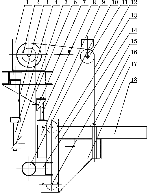
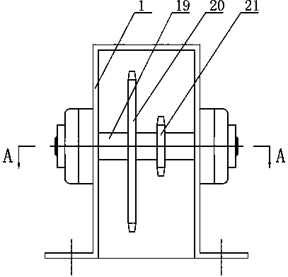
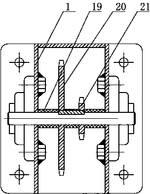
[0018] Such as figure 1 As shown, the lifting mechanism of this embodiment includes a machine base 1, and a driving sprocket 2 is installed in the machine base 1. The driving sprocket 2 is a double-row sprocket, and a support 14 is arranged at the bottom of the machine base 1. The support 14 A driven sprocket 10 is installed on the top, and the driving sprocket 2 and the driven sprocket 10 are engaged and driven through the first chain 6 to form a vertically arranged chain transmission mechanism; the two sides of the first chain 6 pass through the chain links respectively. The fastener is equipped with a first connecting piece 5 and a second connecting piece 7; a first cylinder 3 is installed at the bottom of the base 1, and the first piston rod 4 of the first cylinder 3 is connected with the first connecting piece 5; The second cylinder ...


PUM


Abstract

A lifting mechanism comprises a base. A driving sprocket is mounted in the base, a support is arranged on the lower portion of the base, a driven sprocket is mounted on the support, and the driving sprocket is in meshed transmission with the driven sprocket via a first chain, so that a vertically arranged chain transmission mechanism is formed; a first connector and a second connector are respectively mounted on chain links on two sides of the first chain by fasteners; a first cylinder is mounted at the bottom of the base, and a first piston rod of the first cylinder is connected with the first connector; a second cylinder is mounted on the support, and a second piston rod of the second cylinder is connected with the second connector; a slide groove framework which is parallel to the vertically arranged chain transmission mechanism is arranged on one side of the support, rollers are mounted in the slide groove framework, a bracket capable of sliding along the slide groove framework is connected onto the slide groove framework, and a compaction plate is mounted on the upper portion of the bracket; and a fixed pulley is arranged on one side of the driving sprocket, the driving sprocket is meshed with the fixed pulley via a second chain, and the second chain at one end of the fixed pulley is connected with the compaction plate by a fastener. The lifting mechanism has the advantages of reliability in operation and high precision.

Description

technical field [0001] The invention relates to a lifting mechanism, in particular to a lifting mechanism adopting chain transmission. Background technique [0002] The lifting mechanism is widely used in the machining industry, such as guide rail lifting mechanism and hydraulic lifting mechanism. [0003] In the packaging process of the packaging production line, the packaging process of the packaging production line includes filling, wrapping, sealing and other main processes. Packaging machines are also divided into: filling machines, sealing machines, wrapping machines, multi-functional packaging machines, etc.; packaging production lines are also divided into: forming-filling-sealing packaging production lines, cartoning and boxing packaging production lines, liquid filling machines and their assembly lines Wait. In its production process, it is necessary to use a lifting mechanism to solidify and transport the packaging bags. [0004] The lifting mechanism adopted i...

Claims


Application Information

Patent Timeline
Patent Type & Authority Patents(China)
IPC IPC(8): B65B1/24B65B61/24
Inventor 何海英赵勇智耿耀兴
Owner M & J MACHINERY ENGINEER
Learn More