
Channel state information feedback method and user equipment in multiple base station cooperation process

A technology of channel state information and user equipment, which is applied in the field of communication, can solve the problems of lack of dynamic support for JT and DPS transmission channel state information feedback methods, etc., and achieve the effect of simple implementation and small signaling overhead

Inactive Publication Date: 2013-07-03
SHARP KK
View PDF2 Cites 15 Cited by
  • Summary
  • Abstract
  • Description
  • Claims
  • Application Information

AI Technical Summary

Problems solved by technology

[0060] The purpose of the present invention is to provide a novel channel state information feedback method and user equipment for the lack of a channel state information feedback method that dynamically supports JT and DPS transmission in the prior art

Method used


Image

  • Channel state information feedback method and user equipment in multiple base station cooperation process
  • Channel state information feedback method and user equipment in multiple base station cooperation process
  • Channel state information feedback method and user equipment in multiple base station cooperation process

Examples


example 1

[0107] Example 1: The transmission point set configured by the serving base station 202 for the user equipment 416 includes 2 transmission points (to facilitate the user equipment to use 1 bit to feed back the result of selecting 1 from 2), and the 2 transmission points can be: (1) ports of the base station 202 0 to port 7, a transmission point consisting of a total of 8 ports; (2) port 0 to port 3 of base station 202, port 0 to port 1 of base station 200, and port 2 to port 3 of base station 204, a total of 8 ports launch point.

example 2

[0108] Example 2: The transmission point set configured by the serving base station 202 for the user equipment 416 includes 3 transmission points (to facilitate the user to use 2 bits to feed back the result of choosing 1 from 3), and the 3 transmission points can be: (1) Port 0 of the base station 202 to port 7, a transmission point consisting of a total of 8 ports; (2) port 0 to port 3 of the base station 202, port 0 to port 1 of the base station 200, and port 2 to port 3 of the base station 204, a total of 8 ports constituted Transmission point; (3) Port 0 to port 3 of the base station 202, port 3 to port 4 of the base station 200, and port 0 to port 1 of the base station 204, a transmission point consisting of 8 ports in total.

example 3

[0109]Example 3: The transmission point set configured by the serving base station 202 for the user equipment 416 includes 4 transmission points (to facilitate the user to use 2 bits to feed back the result of selecting 1 from 4), and the 4 transmission points can be: (1) port 0 of the base station 202 to port 7, a transmission point consisting of a total of 8 ports; (2) port 0 to port 3 of the base station 202, port 0 to port 1 of the base station 200, and port 2 to port 3 of the base station 204, a total of 8 ports constituted Transmission point; (3) port 0 to port 3 of base station 202, port 3 to port 4 of base station 200, and port 0 to port 1 of base station 204, a transmission point consisting of a total of 8 ports; (4) port of base station 204 0 to port 3, a total of 4 ports constitute the emission point. It should be pointed out that selecting the fourth transmission point by the user equipment is equivalent to selecting the entire base station 204 . That is, the tran...


PUM


Abstract

The invention provides a channel state information feedback method and user equipment in a multiple base station cooperation process. The channel state information feedback method includes obtaining a collection of emission points from service base stations; determining a channel rank index (RI) for joint transmitting (JT) processing; determining a sub channel pre-coding matrix index (PMI) for the JT processing; and feeding channel state information back to the service base stations. If the service base stations need to determine the RI and / or the sub PMI for the JT processing according to feedback, the channel state information which is fed back accordingly comprises the determined RI for the JT processing and / or the determined sub PMI for the JT processing.

Description

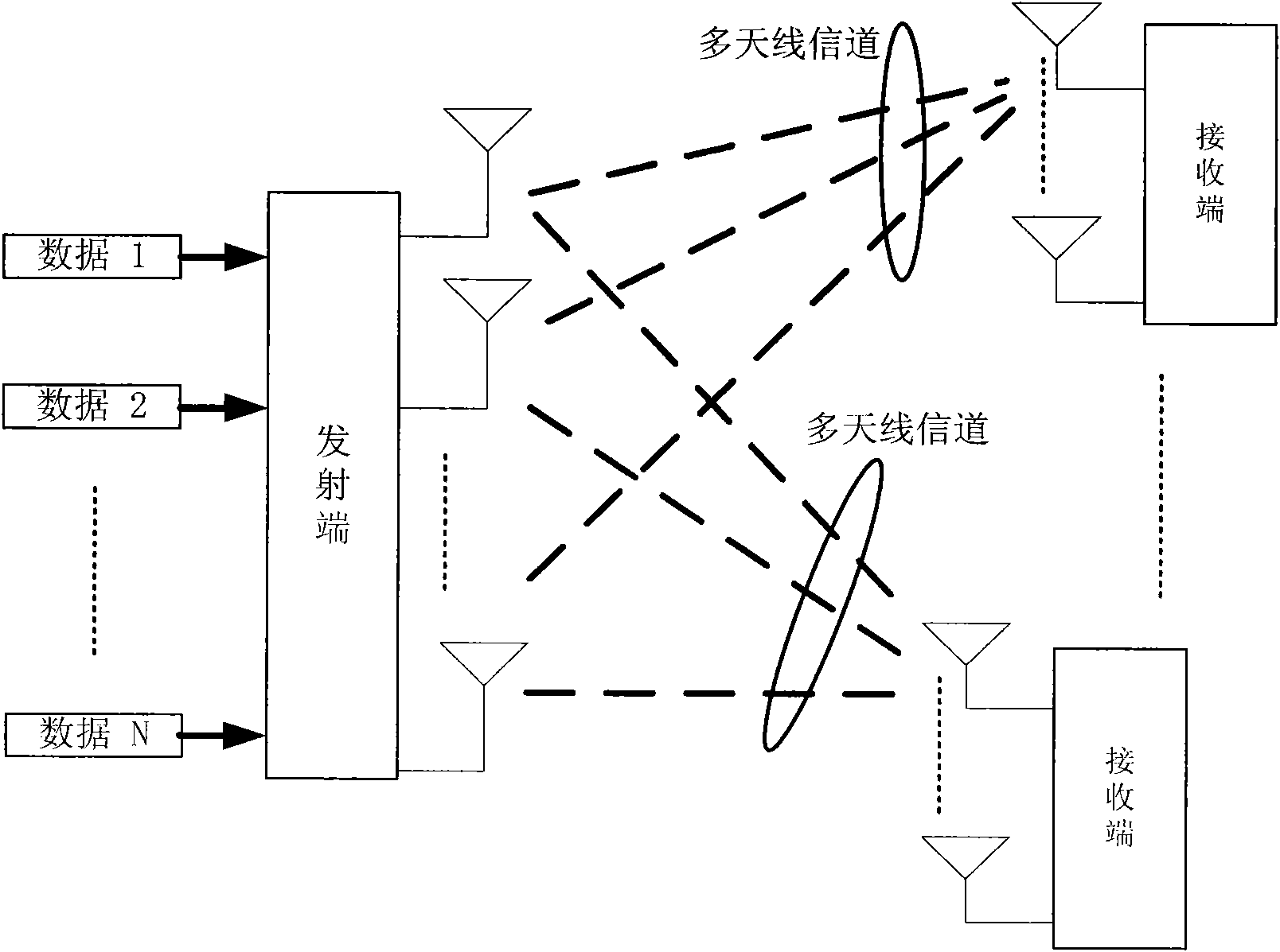
technical field [0001] The present invention relates to the field of communication technology, and more specifically, relates to a channel state information feedback method in multi-base station cooperation mode and corresponding user equipment. Background technique [0002] Multiple Input Multiple Output (MIMO, Multiple In Multiple Out) wireless transmission technology configures multiple antennas at the transmitting end and the receiving end, utilizes space resources in wireless transmission, and obtains space multiplexing gain and space diversity gain. Information theory studies show that the capacity of MIMO systems increases linearly with the minimum number of transmit antennas and receive antennas. A schematic diagram of a MIMO system is shown in figure 1 As shown, where the multiple antennas of the transmitting end and the receiving end constitute a multi-antenna wireless channel, including airspace information. In addition, Orthogonal Frequency Division Multiplex (...

Claims


Application Information

Patent Timeline
IPC IPC(8): H04W88/02H04L1/00
CPCH04W16/28H04B7/0456H04B7/0617H04B7/0626H04L1/0026H04L1/06H04L5/0035H04L5/0057
Inventor 丁铭杨曾黄磊
Owner SHARP KK
Learn More