
Strip postprocessing wire centring device and usage thereof

A centering device and post-processing technology, applied in auxiliary devices, auxiliary welding equipment, welding/cutting auxiliary equipment, etc., can solve problems such as potential safety hazards, improve production efficiency, ensure straightness, and avoid unsafe operating behaviors Effect

Inactive Publication Date: 2013-07-03
CISDI ENG CO LTD
View PDF10 Cites 0 Cited by
  • Summary
  • Abstract
  • Description
  • Claims
  • Application Information

AI Technical Summary

Problems solved by technology

[0004] Since the existing centering device cannot lift the looper smoothly, in order to ensure the welding quality and prevent the strip steel from sliding back and forth after the looper is lifted, the strip steel has to be manually pressed down by hand. After the centering is completed, the clamp clamps the strip steel Only dare to let go, the workers' hands and bodies are too close to the fast-moving mechanical mechanism, which poses a great safety hazard

Method used


Image

  • Strip postprocessing wire centring device and usage thereof

Examples


Embodiment 1

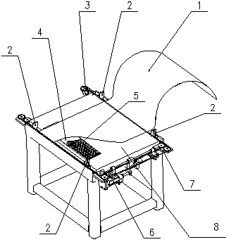
[0018] Embodiment 1, a strip post-processing line centering device, which is a four-point closing centering device, includes a centering platform, and four centering blocks 2 and fixed pulleys 3 are arranged on the centering platform and passed through The steel rope 7 is connected to the cylinder 6, and an electromagnet unit 5 is arranged on the centering platform. An insulating backing plate 4 is arranged on the electromagnet unit 5. The insulating backing plate 4 is a plastic backing plate with lines, and the lines are consistent with the operation of the unit. The direction is vertical; 100 small electromagnet units are divided into 25 groups by superposition and combination, the first group is composed of electromagnets numbered 1 to 4, the second group is composed of electromagnets numbered 1 to 8..., and so on The 25th group is composed of electromagnets numbered 1 to 100, the suction force of the 1st group to the 25th group is from small to large, and the electromagnet ...

Embodiment 2

[0021] Embodiment 2, a strip post-processing line centering device, which is a four-point closing centering device, includes a centering platform, and four centering blocks 2 and fixed pulleys 3 are arranged on the centering platform and passed through The steel rope 7 is connected with the cylinder 6, and the centering frame is provided with an electromagnet unit 5, the electromagnet unit 5 is a whole piece of electromagnet, an insulating backing plate 4 is set on the electromagnet unit 5, and the insulating backing plate 4 is a plastic backing plate And with lines, the lines are perpendicular to the running direction of the unit.

[0022] The method of using the centering device of the post-processing line of the strip: after the operation of the strip steel 1 is completed, the tail of the strip and the head of the next roll of strip steel 1 are respectively run to the front and rear of the welding machine or the sewing machine. On the centering stand, according to the thick...


PUM


Abstract

The invention discloses a strip postprocessing wire centring device, which belongs to a four-point folding centring device, and is characterized in that an electromagnet unit is arranged on a centring rack and is connected with a control circuit, and an insulating padding plate with veins vertical to the running direction of a unit is arranged on the electromagnet unit. According to the invention, an electromagnet is arranged on the centring rack of the four-point folding centring device, and the insulating padding plate is arranged between the electromagnet and a strip steel; the strip steel can be effectively prevented from sliding forwards and backwards, but the horizontal movement of the strip steel is not influenced; the butt joint of the strip steel can be automatically completed in a free state, and the straightness of the strip steel subjected to butt joint is guaranteed; unsafe operation behavior in production can be avoided; and not only is production quality improved, but also production efficiency is improved.

Description

technical field [0001] The invention relates to a strip post-processing line centering device and a using method thereof. Background technique [0002] On the post-processing continuous production line of low-carbon steel or non-ferrous metal strips such as galvanizing line, continuous annealing line, color coating line, degreasing line, etc., after the raw material production of the previous roll is completed, its tape tail needs to be aligned with the lead of the next roll. They are connected together by welding or sewing to ensure the continuous production of the unit. Before welding or sewing, the belt head and belt tail need to be centered with the center line of the unit as the standard to ensure the straightness after welding or sewing, otherwise it is easy to cause deviation and break the belt during operation. Because the four-point closing and centering device has simple structure, low cost, and convenient maintenance and use, it is widely used in strip post-proce...

Claims


Application Information

Patent Timeline
IPC IPC(8): B23K37/04
Inventor 刘迁
Owner CISDI ENG CO LTD
Learn More