Eureka AIR delivers breakthrough ideas for toughest innovation challenges, trusted by R&D personnel around the world.

Fatigue test device and method for axle

A fatigue test and test device technology, applied in the field of rail transit, can solve the problems of not being able to carry out the fatigue test of the axle neck and not being able to comprehensively evaluate the rationality of the wheel and axle structure.

Active Publication Date: 2013-06-26
CRRC QINGDAO SIFANG CO LTD
View PDF7 Cites 25 Cited by
  • Summary
  • Abstract
  • Description
  • Claims
  • Application Information

AI Technical Summary

Problems solved by technology

[0004] The test device commonly used in the above-mentioned prior art cannot carry out the fatigue test of the journal position, and the remedial method can only be to perform corresponding conversion on the test data of other parts to approximate the fatigue strength coefficient of the journal
[0005] Moreover, the test device based on the above-mentioned structure and test method can only apply radial load to the axle without axial load and data detection and derivation functions.
[0006] Therefore, it is still impossible to systematically establish the corresponding relationship between load and stress bending, or the fatigue coefficient of the journal by using the existing wheel axle fatigue test device, and it is still impossible to comprehensively evaluate the rationality of the wheel axle structure design and materials.

Method used


Image

  • Fatigue test device and method for axle
  • Fatigue test device and method for axle
  • Fatigue test device and method for axle

Examples


Embodiment 1

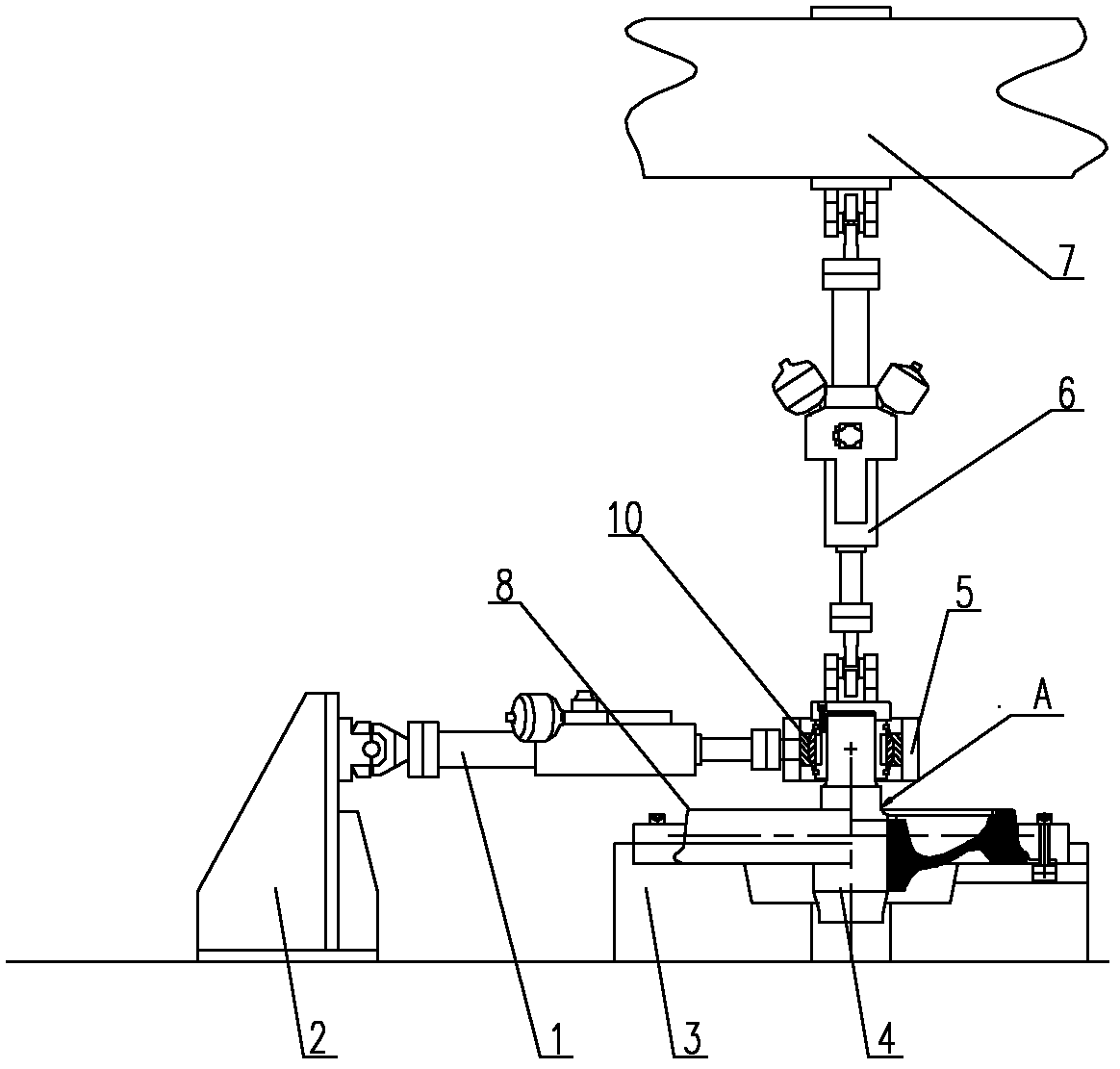
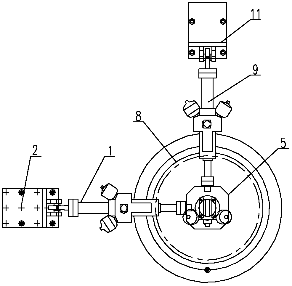
[0036] Example 1, such as figure 1 and figure 2 As shown, the test device for realizing the fatigue test method of the axle journal mainly includes a loading beam 7 and a platform 3 . in,

[0037] radially fix the wheel 8 on the platform 3, and axially fix the end of the tested wheel shaft 4;

[0038] At the journal of the tested wheel shaft 4, the rolling bearing 10 is installed inside the mounting seat 5, and the vertical actuator 6, the transverse actuator 1 and the longitudinal actuator 9 are respectively connected to the mounting seat 5.

[0039] The axle journal fatigue test method is to paste a stress detection sheet at the corner of the tested wheel axle 4 adjacent to the wheel 8;

[0040] During the journal fatigue test, the tested wheel shaft 4 rotates at a uniform speed in the circumferential direction, and the above-mentioned vertical actuator 6, lateral actuator 1 and longitudinal actuator 9 apply loads to the journal of the tested wheel shaft 4 respectively....

Embodiment 2

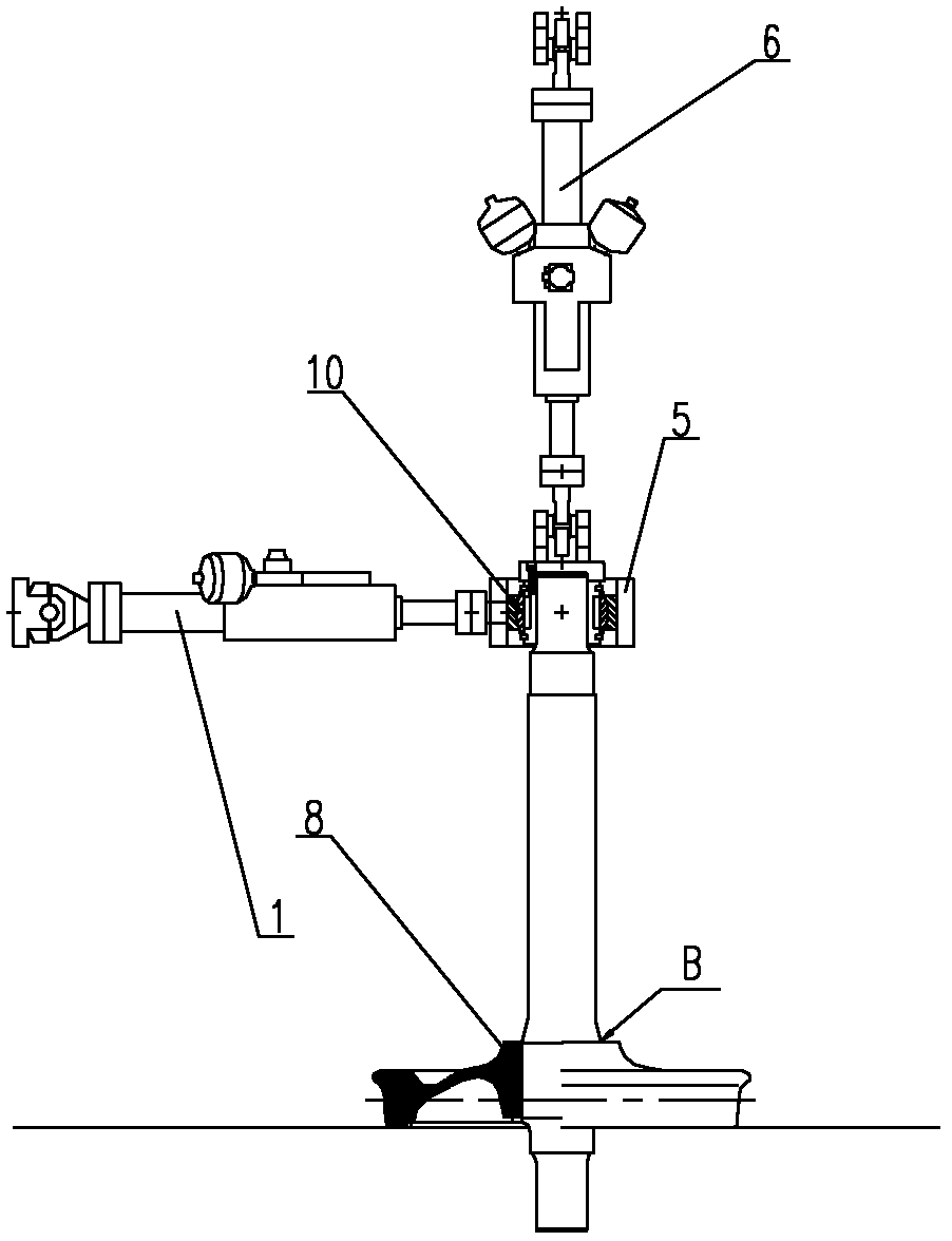
[0046] Example 2, such as image 3 As shown, the difference from Example 1 is that during the shaft fatigue test, the shaft end of the tested wheel shaft 4 is installed inside the mounting seat 5 through the rolling bearing 10, and the vertical actuator 6 and the lateral actuator 1 and the longitudinal cylinder 9 are connected to the mounting base 5 respectively.

[0047] Other test devices and test methods are similar to those in Example 1, and will not be repeated here.


PUM


Abstract

The invention relates to a fatigue test device and method for an axle. The fatigue test device for the axle comprises a loading beam and a platform. A wheel is radially fixed on the platform, and the end of an axle to be tested is fixed axially; and a vertical actuating cylinder, a transverse actuating cylinder and a longitudinal actuating cylinder are connected to a journal of the axle to be tested respectively. The journal of the axle to be tested is mounted in a mounting seat through a rolling bearing; and the vertical actuating cylinder, the transverse actuating cylinder and the longitudinal actuating cylinder are connected with the mounting seat respectively. On the basis of the test device and method, the fatigue test of the journal, an axle body and a wheel disk can be achieved comprehensively; a test mode of journal rotation bending and axial loading can be set comprehensively aimed at a fatigue test and axial loading solution towards the journal, and accordingly, the fatigue test comprehensiveness of the whole axle is improved.

Description

technical field [0001] The invention relates to a device and a method for implementing a fatigue test on a journal of a wheel axle of a rail vehicle and belongs to the technical field of rail transportation. Background technique [0002] With the rapid popularization of domestic urban rail transit and the substantial increase in vehicle speed, higher design and use requirements are put forward for the bogie frame that carries the vehicle body and transmits traction. Among them, the axle is an important component of the bogie, and the fatigue test for the axle is the guarantee for long-term, high-speed and safe operation. [0003] At present, domestic test devices for wheel shafts are mainly divided into eccentric excitation type, rotating bending type, integral rolling type and simply supported beam rotating bending type structure, and corresponding test methods are limited to fatigue tests on the axle body and web. [0004] The test device commonly used in the above-mentio...

Claims


Application Information

Patent Timeline
Patent Type & Authority Applications(China)
IPC IPC(8): G01M17/10G01N3/36
Inventor 李亚波张洪刘为亚陈一萍李庆升
Owner CRRC QINGDAO SIFANG CO LTD
Why Eureka
Eureka Blog
Learn More