
Multi-point driving electric traction coal mining machine

A multi-point drive, shearer technology, applied in the direction of drive device, earthwork drilling, slitting machinery, etc., can solve the problem of insufficient traction power, and achieve the effect of simple and compact structure, high reliability, and improved mining efficiency

Inactive Publication Date: 2015-01-21
CHINA UNIV OF MINING & TECH
View PDF6 Cites 0 Cited by
  • Summary
  • Abstract
  • Description
  • Claims
  • Application Information

AI Technical Summary

Problems solved by technology

[0003] Purpose of the invention: the purpose of the invention is to propose a multi-point drive electric traction shearer to solve the problem of insufficient traction power in the existing drum electric traction shearer

Method used


Image

  • Multi-point driving electric traction coal mining machine
  • Multi-point driving electric traction coal mining machine
  • Multi-point driving electric traction coal mining machine

Examples


Embodiment 1

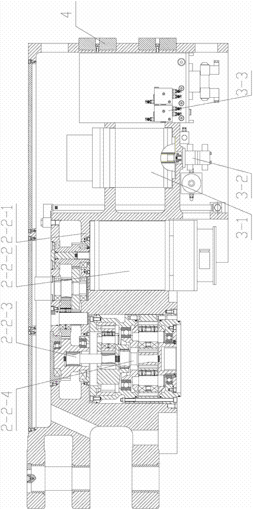
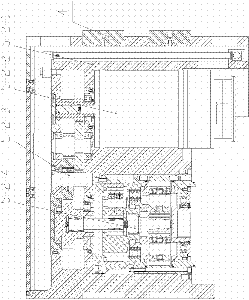
[0026] Such as Figures 1 to 3 As shown, the multi-point drive electric traction shearer of the present invention comprises a left cutting part 1, an electric control box 6 and a right cutting part 8, and the left cutting part 1 and the right cutting part 8 are respectively arranged on the On both sides of the fuselage, the electric control box 6 is arranged in the middle part of the fuselage of the coal mining machine. A left pulling part is set between the left cutting part 1 and the electric control box 6, and a right pulling part is set between the right cutting part 8 and the electric control box 6.

[0027] The left traction part comprises a first traveling case 2-1, a first fixed case 2-2, a second traveling case 5-1 and a second fixed case 5-2. The right traction part comprises the 3rd fixed box 7-1 and the 3rd traveling box 7-2. Both the left end of the first fixed box 2-2 and the left cutting part 1 and the right end of the third fixed box 7-1 and the right cutting...

Embodiment 2

[0033] In real-time example 2, the left traction part of the multi-point drive electric traction coal shearer is the same as that of embodiment 1, and the fourth fixed box 8-1 and the fourth traveling box 8-2 are added to the right traction part.

[0034] Such as Figure 4 As shown, the multi-point drive electric traction coal shearer of the present invention comprises a left cutting part 1, an electric control box 6 and a right cutting part 9, and the left cutting part 1 and the right cutting part 9 are arranged on the shearer respectively. On both sides of the fuselage, the electric control box 6 is arranged in the middle part of the fuselage of the coal mining machine. A left pulling part is set between the left cutting part 1 and the electric control box 6, and a right pulling part is set between the right cutting part 9 and the electric control box 6.

[0035] The left traction part comprises a first traveling case 2-1, a first fixed case 2-2, a second traveling case 5-1...


PUM


Abstract

The invention discloses a multi-point driving electric traction coal mining machine which comprises a left cutting part, an electric control cabinet and a right cutting part, wherein a left traction part is arranged between the left cutting part and the electric control cabinet; a right traction part is arranged between the right cutting part and the electric control cabinet; the left traction part comprises a first fixed box and a second fixed box; the right end of the second fixed box is connected with the electric control cabinet; the left end of the second fixed box is connected with the right end of the first fixed box; the bottom of the second fixed box is connected with a second travelling box; the left end of the first fixed box is connected with the left cutting part; the bottom of the first fixed box is connected with a first travelling box; the right traction part comprises a third fixed box; the left end of the third fixed box is connected with the electric control cabinet; the right end of the third fixed box is connected with the right cutting part; the bottom of the third fixed box is connected with a third travelling box; and the third fixed box and the first fixed box have the same structures and are arranged in a symmetrical way. The coal mining machine is driven by a plurality of points at the same time, meets the mining demands of a down-hole steeply inclined coal seam, and improves the mining efficiency of the down-hole steeply inclined coal seam.

Description

technical field [0001] The invention belongs to the technical field of mining machinery and equipment, in particular to a drum-type electric traction shearer suitable for mining steeply inclined coal seams in coal mines. Background technique [0002] Drum-type electric traction shearers are generally used for mining steeply inclined coal seams in coal mines. The existing drum-type electric traction shearer is usually provided with a traction section on both sides of the middle box, and each traction section is provided with a motor, which ensures the normal running of the shearer through the motor drive. However, considering that the geological structure of our country is relatively complex, the mining of steeply inclined coal seams is relatively difficult, the power of the traction part driven by a single motor is insufficient, it is difficult to realize mechanization, the risk factor is large, the mining efficiency is low, and the working environment is harsh. Many steeply...

Claims


Application Information

Patent Timeline
Patent Type & Authority Patents(China)
IPC IPC(8): E21C29/22E21C31/02E21C31/08
Inventor 刘送永杜长龙郑加强崔新霞刘晓辉刘增辉
Owner CHINA UNIV OF MINING & TECH
Learn More