
Packing case

A packaging box and box body technology is applied in the field of packaging boxes with a blocking angle structure on the inside, which can solve the problems of limited impact force on the side wall and easy damage to the side wall.

Active Publication Date: 2015-04-08
AU OPTRONICS CORP
View PDF6 Cites 0 Cited by
  • Summary
  • Abstract
  • Description
  • Claims
  • Application Information

AI Technical Summary

Problems solved by technology

However, the embedding range of this hard structural part is still limited to the structural part above the bottom of the storage space in the box, and the hard structural part is inserted downward from the top of the box, so the side wall must correspond to the structure with holes for The insertion of hard structural parts causes the impact force that the side wall can withstand here is still limited, and the side wall here is still easily damaged when encountering a large impact

Method used


Image

  • Packing case
  • Packing case
  • Packing case

Examples


Embodiment Construction

[0043] The technical solution of the present invention will be described in detail below in conjunction with the accompanying drawings and specific embodiments to further understand the purpose, solution and effect of the present invention, but it is not intended to limit the scope of protection of the appended claims of the present invention.

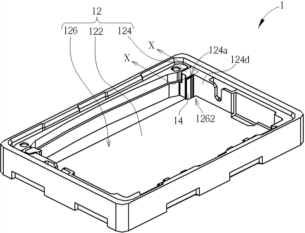
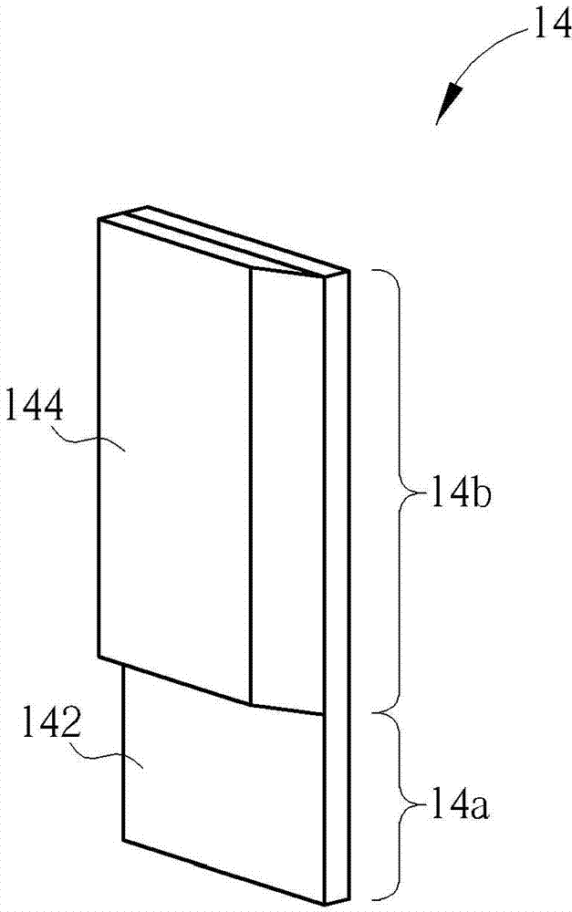
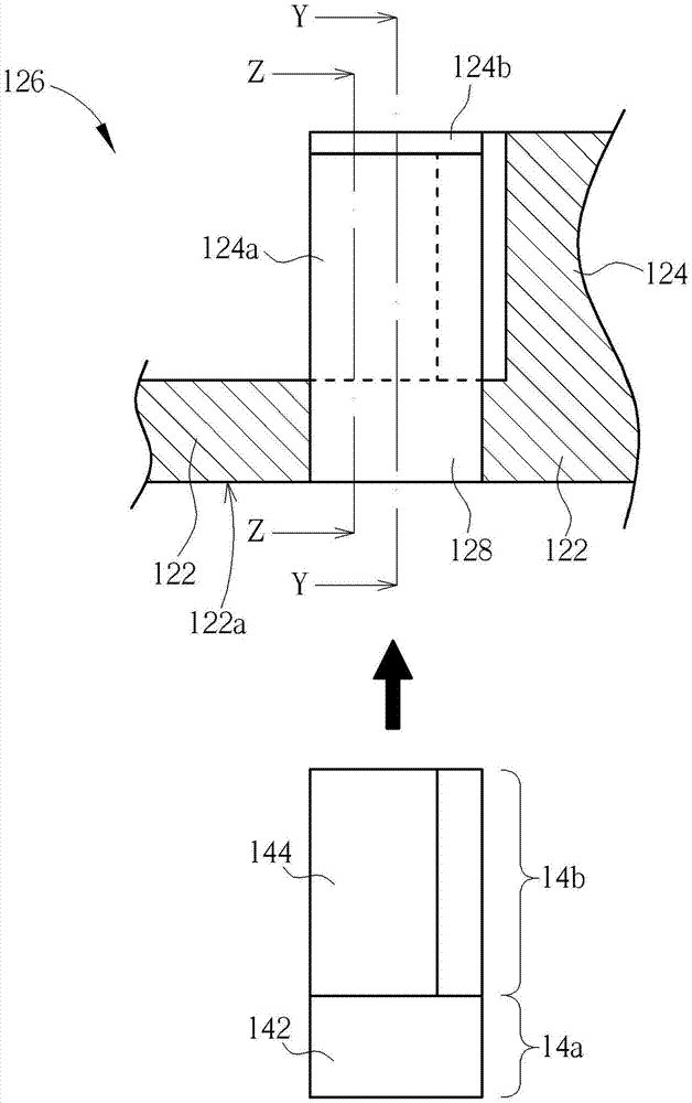
[0044] see figure 1 , which is a schematic diagram of a packing box 1 according to a preferred embodiment of the present invention. The packaging box 1 includes a box body 12 and a corner piece 14 . The box body 12 includes a bottom 122 and a side wall structure 124. The side wall structure 124 is arranged around the bottom 122 to form a housing space 126. The housing space 126 has a corner 1262 adjacent to one of a plurality of corners of the side wall structure 124 and Between the bottom 122. The corner block 14 is disposed at the corner 1262 . In practice, the box body 12 will be packaged with a top cover, but the present inventi...


PUM


Abstract

The invention discloses a packing case, which comprises a case body and a corner baffle member. The case body comprises a bottom and a side wall structure. The side wall structure is arranged in a way to surround the bottom so as to form an accommodating space. The accommodating space comprises a corner. The corner baffle member is arranged on the corner and comprises an insertion part and a buffer part connected with the insertion part. The insertion part is inserted into the bottom. The buffer part is exposed on the accommodating space and adjacent to one wall face of the side wall structure. In this way, when an object accommodated inside the accommodating space has impacts on the corner baffle member, the impacts are directly transmitted to the bottom through the corner baffle member. The problem that a conventional packing case body cannot effectively bear the impacts through the side wall is thus solved.

Description

technical field [0001] The invention relates to a packing box, in particular to a packing box with a corner structure inside. Background technique [0002] Fragile objects, such as glass (panel), are usually packaged in boxes to avoid damage or breakage due to collisions during transportation. And in order to make the box body capable of absorbing impact energy to avoid brittle objects from being damaged or broken due to absorbing too much impact energy, the box body is mostly made of foam material. However, if the foam material is too soft, its local structural strength is insufficient, and the deformation amount is too large when the local impact energy is absorbed, which will easily make the brittle objects loose in the box, which will cause slight shaking during subsequent transportation. The object is damaged or shattered by a collision. Therefore, at present, the inner side of the box body, especially the corner, is provided with a stopper with a soft surface, so as ...

Claims


Application Information

Patent Timeline
Patent Type & Authority Patents(China)
IPC IPC(8): B65D77/26
Inventor 詹黛玲茅仲宇丁崇宽
Owner AU OPTRONICS CORP
Learn More