
Method and device of screening digital pulse signal

A digital pulse and pulse signal technology, applied in the field of signal processing, can solve the problems of poor real-time performance, unsatisfactory signal discrimination effect, and narrow application range, and achieve the effect of high real-time performance.

Inactive Publication Date: 2013-06-19
UNIV OF SCI & TECH OF CHINA
View PDF4 Cites 10 Cited by
  • Summary
  • Abstract
  • Description
  • Claims
  • Application Information

AI Technical Summary

Problems solved by technology

[0004] However, the current DPSD technology still has some problems. First, the real-time performance is poor and the dead time is large; second, because only the ratio of integrals in different areas of the waveform is used as the basis for judgment, the signal discrimination effect is not ideal, and it can only adapt to Some specific measurements, the scope of application is very narrow

Method used


Image

  • Method and device of screening digital pulse signal
  • Method and device of screening digital pulse signal
  • Method and device of screening digital pulse signal

Examples


Embodiment 1

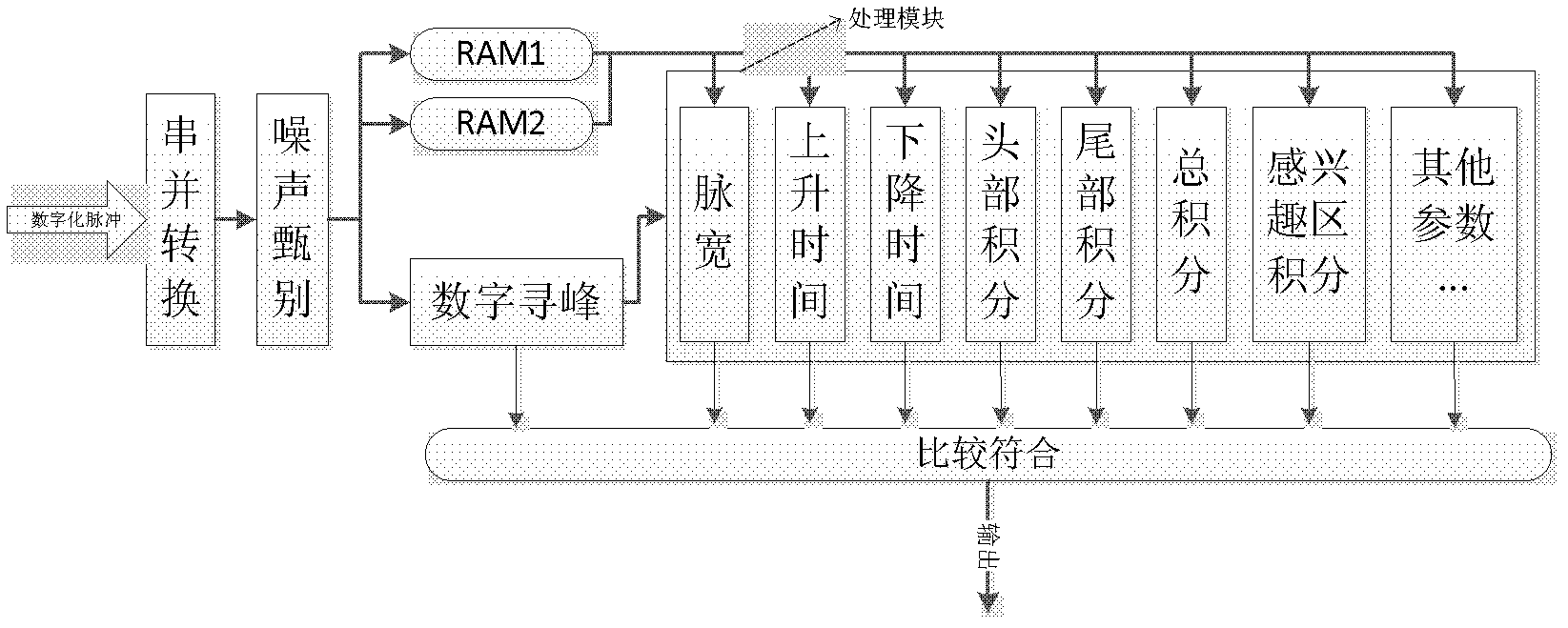
[0020] This embodiment provides a multi-criteria parallel pipeline real-time online pulse signal discrimination method, the complete processing flow of the method is as follows figure 1 shown. After the pulse signal to be screened is processed by signal conditioning and anti-aliasing filtering, it enters the high-speed ADC to complete the digital processing of the pulse signal to obtain a digital pulse signal, and then uses FPGA (Field Programmable Gate Array, Field Programmable Gate Array) to multiplex the digital pulse signal. Criteria are processed in parallel in real time.

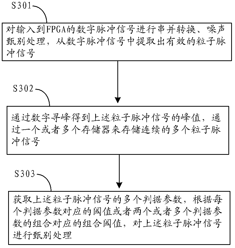
[0021] A schematic diagram of the principle of a method for discriminating and processing digital pulse signals inside the FPGA provided by this embodiment is as follows figure 2 As shown, the specific processing flow of the method is as follows image 3 As shown, the following processing steps are included:

[0022] Step S301 , performing serial-to-parallel conversion and noise screening processin...

Embodiment 2

[0038]This embodiment provides a device for discriminating and processing digital pulse signals, and its specific structure is as follows: Figure 4 As shown, the following modules are included:

[0039] The threshold value setting module 41 is used for setting the threshold value of each criterion parameter of the digital pulse signal respectively.

[0040] Criterion parameter acquisition module 42, is used for adopting the multiple criterion parameters of the digital pulse signal to be discriminated in real time by adopting the parallel pipeline operation mode, the multiple criterion parameters of described digital pulse signal comprise: pulse width, rise time, fall One or more of time, waveform total integration, waveform head integration, waveform tail integration, and waveform ROI integration.

[0041] Judgment processing module 43, used for judging that the number The pulse signal is an effective digital pulse signal.

[0042] Further, the device may also include:

...


PUM


Abstract

The invention relates to a method and a device of screening digital pulse signal. The method mainly comprises a step of respectively setting a threshold value of each criterion parameter of the digital pulse signal. The method comprises a step of using a parallel stream line working way to capture a plurality of the criterion parameters of the digital pulse signal in real time, a step of judging whether each criterion parameter conforms to the set threshold value, and a step of judging the digital pulse signal as an effective digital pulse signal when each criterion parameter of the plurality of the criterion parameter conforms to the set threshold value. Because of adoption of the real-time dealing method of the multi-criterion parallel stream line, real-time performance can be improved, the digital pulse signal can be regarded as the criterion parameter to conduct grain screening only if wave forms of the digital pulse signal are different, and therefore, pulses with different wave forms can be distinguished to the utmost.

Description

technical field [0001] The invention relates to the technical field of signal processing, in particular to a method and device for discriminating digital pulse signals. Background technique [0002] PSD (Pulse Shape-discrimination, pulse shape discrimination) technology is mainly aimed at the difference of pulse shape to realize particle selection. The traditional PSD technology is mainly based on APSD (Analog PSD, analog pulse waveform discrimination), which is mostly realized by charge integration and zero-crossing discrimination. APSD has high precision, but the dynamic range of the count rate is low, there is no reprocessing capability, and the circuit is complex and the integration level is low. [0003] In recent years, with the continuous improvement of ADC (Analogue to Digital Converter, analog-to-digital converter) performance, DPSD (digital PSD, digital pulse waveform discrimination) technology has begun to be widely used. DPSD usually uses a high-speed ADC to sa...

Claims


Application Information

Patent Timeline
IPC IPC(8): H03K5/125
Inventor 阴泽杰李世平杨青巍徐修峰曹宏睿袁国梁
Owner UNIV OF SCI & TECH OF CHINA
Learn More