
Liquid crystal display device

A liquid crystal display device and display area technology, which is applied in the directions of instruments, nonlinear optics, optics, etc., can solve problems such as disconnection of contact holes and poor shorting bar area, and achieve the effect of improving reliability and improving wiring reliability.

Active Publication Date: 2013-06-19
SHANGHAI AVIC OPTOELECTRONICS
View PDF5 Cites 10 Cited by
  • Summary
  • Abstract
  • Description
  • Claims
  • Application Information

AI Technical Summary

Problems solved by technology

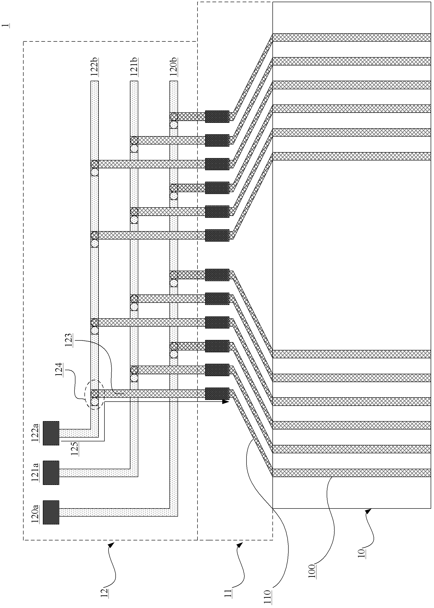
[0013] The purpose of the present invention is to provide a liquid crystal display device to solve the problem that defects often occur in the shorting bar area in the prior art, especially the problem of disconnection at the contact hole

Method used


Image

  • Liquid crystal display device
  • Liquid crystal display device
  • Liquid crystal display device

Examples


Embodiment 1

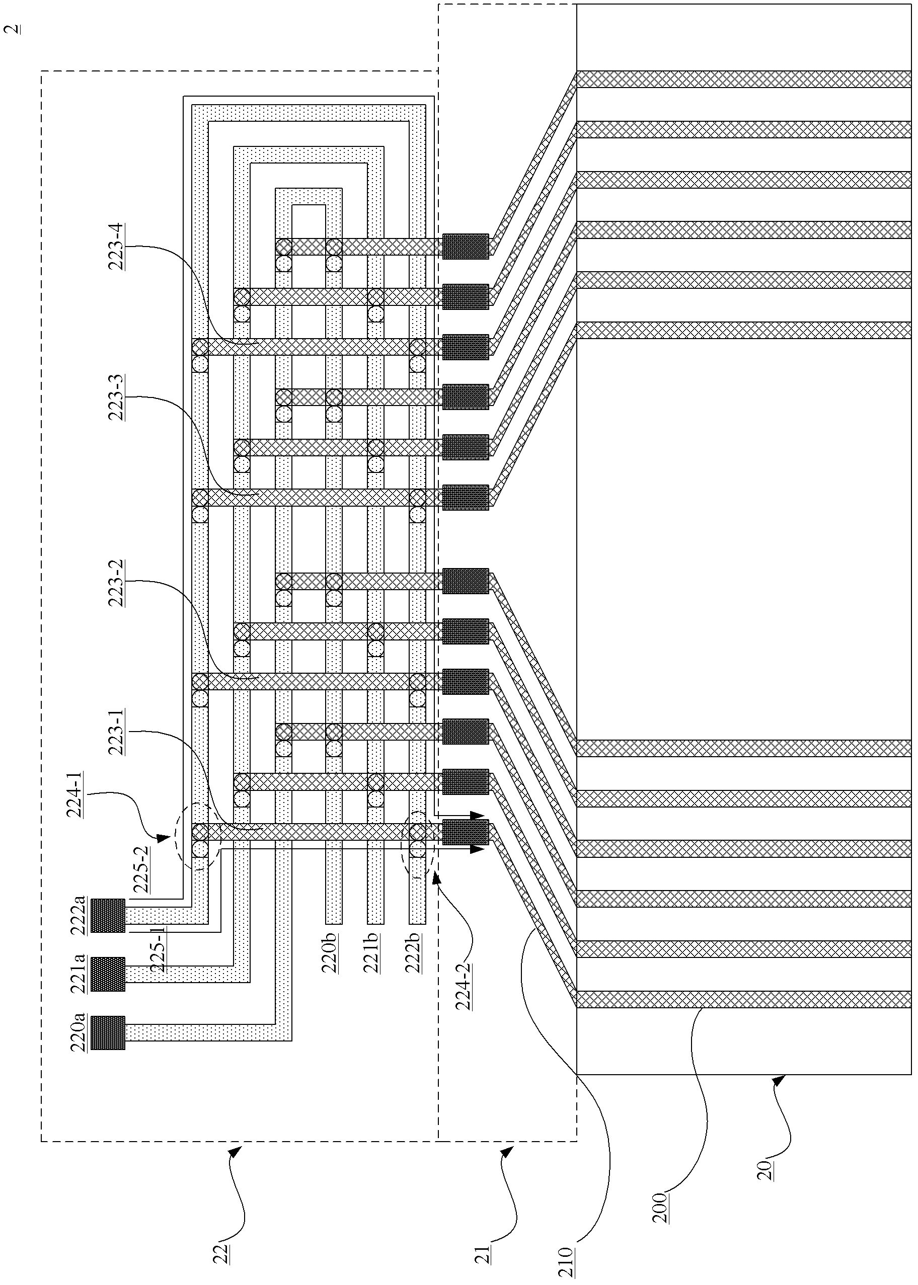
[0031] Please refer to figure 2 , which is a schematic structural diagram of a liquid crystal display device according to Embodiment 1 of the present invention. Such as figure 2 As shown, the liquid crystal display device 2 includes:

[0032] The shorting bar area 22, the shorting bar area 22 includes: several detection terminals, each detection terminal is connected with several shorting bars, and each shorting bar is connected with several connecting lines, wherein each connecting line passes through at least The two signal transmission channels are electrically connected to the detection terminals;

[0033] a peripheral area 21, the peripheral area 21 is electrically connected to the shorting bar area 22;

[0034] A display area 20 , the display area 20 is electrically connected to the peripheral area 21 .

[0035] In this embodiment, the peripheral area 21 is electrically connected to the shorting bar area 22 through a connection line, the peripheral area 21 includes...

Embodiment 2

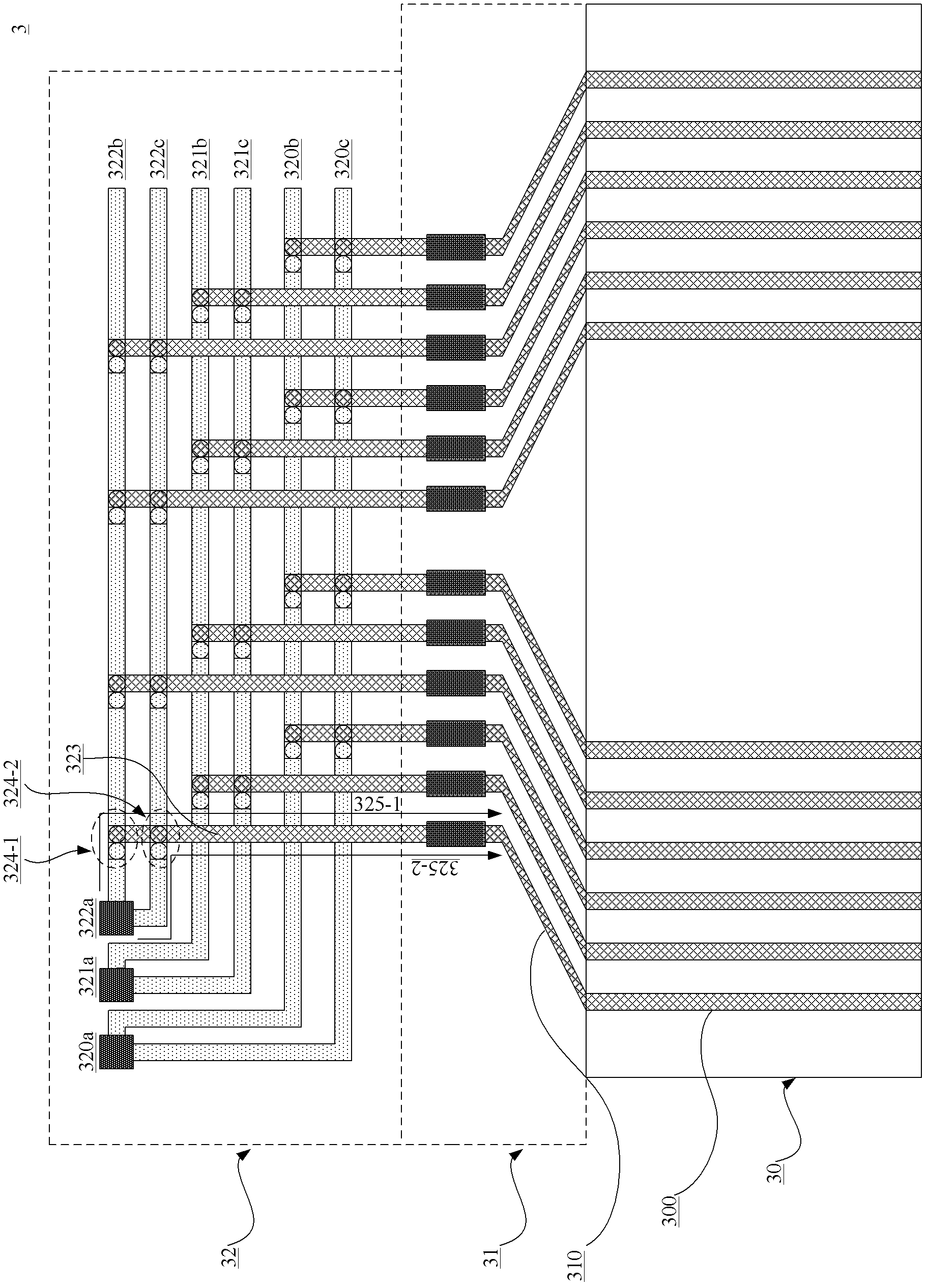
[0047] Please refer to image 3 , which is a schematic structural diagram of a liquid crystal display device according to Embodiment 2 of the present invention. Such as image 3 As shown, the liquid crystal display device 3 includes:

[0048] The shorting bar area 32, the shorting bar area 32 includes: several detection terminals, each detection terminal is connected with several shorting bars, and each shorting bar is connected with several connecting lines, wherein each connecting line passes through at least The two signal transmission channels are electrically connected to the detection terminals;

[0049] a peripheral area 31, the peripheral area 31 is electrically connected to the shorting bar area 32;

[0050] A display area 30 , the display area 30 is electrically connected to the peripheral area 31 .

[0051] In this embodiment, it is also realized that each connection line is electrically connected to the detection terminal through two signal transmission channel...


PUM


Abstract

The invention provides a liquid crystal display device which comprises a short circuiting bar area, a periphery area and a display area, wherein the short circuiting bar area comprises a plurality of detection terminals, each detection terminal is connected with a plurality of short circuiting bars, each short circuiting bar is connected with a plurality of connecting lines, each connecting line is electrically connected with the detection terminals through at least two signal transmission channels; the periphery area is electrically connected with the short circuiting bar area; and the display area is electrically connected with the periphery area. Due to the fact that each connecting line is electrically connected with the detection terminals through at least two signal transmission channels in the liquid crystal display device, even if one signal transmission channel breaks, the detection operation can be carried out through the other signal transmission channel, reliability of the liquid crystal display device is improved, and wire arrangement reliability in the short circuiting bar area is improved particularly.

Description

technical field [0001] The invention relates to the field of display devices, in particular to a liquid crystal display device. Background technique [0002] The liquid crystal display device includes a display area composed of matrix display pixels, the display area has a plurality of gate lines extending in the row direction of the display pixels and a plurality of data lines extending in the column direction of the display pixels. Wire. Switching elements and pixel electrodes connected to the switching elements are provided at the intersections of these gate lines and data lines. The switching elements are, for example, thin film transistors (switching elements). The signal from the pole line and the signal from the data line are sent to each corresponding pixel electrode. [0003] The liquid crystal display device further includes a peripheral area, and the peripheral area includes data lines arranged in a fan shape and gate lines arranged in a fan shape. One end of t...

Claims


Application Information

Patent Timeline
Patent Type & Authority Applications(China)
IPC IPC(8): G02F1/13
Inventor 胡文晓
Owner SHANGHAI AVIC OPTOELECTRONICS
Learn More