
Indicator and method for cable core correction and transformer tripping outlet correction

A cable core and transformer technology, applied in the field of cable core proofing and transformer tripping exit proofing indicators and proofing, can solve the problems of cumbersome cable core proofing work, damage to equipment accidents, poor accuracy, etc., to achieve reliable performance, detection and proofreading Fast and accurate results with intuitive and accurate results

Active Publication Date: 2013-06-19
STATE GRID CORP OF CHINA +1
View PDF12 Cites 3 Cited by
  • Summary
  • Abstract
  • Description
  • Claims
  • Application Information

AI Technical Summary

Problems solved by technology

The proofreading work of the cable core wire is cumbersome and requires carefulness and meticulousness. A slight negligence will damage the equipment or cause an accident
Background Art When checking the core wires of cables on site, two people usually use walkie-talkies and one person uses a multimeter to test and verify each core; for example, if the cable has 10 cores, the total number of times of checking is at most 1+2+3+...+9+ 10=55 times, the workload is huge
Especially for microcomputer-based transformers, there are many types of protection, and the tripping outlets of each function can be freely combined. The function can control 10 outlets; at present, the potential test is carried out one by one by a special person according to the function. Since the tripping outlet of each function of the protection device is editable, taking 3 functions and 10 outlets as an example, one function needs to be tested. 10 verification tests, a total of 30 tests are required, resulting in low efficiency and poor accuracy when measuring personnel

Method used


Image

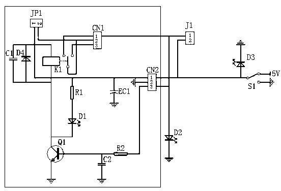
  • Indicator and method for cable core correction and transformer tripping outlet correction
  • Indicator and method for cable core correction and transformer tripping outlet correction

Examples


Embodiment Construction

[0018] The present invention will be further described through the embodiments below in conjunction with the accompanying drawings.

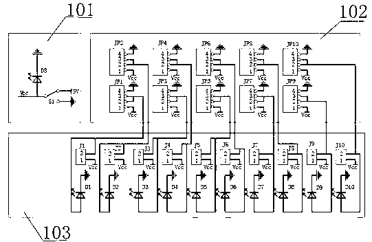
[0019] In this embodiment, there are 10 relay action holding modules connected in parallel, which respectively correspond to 10 pairs of sockets J1, J2...J10 (leading wire ends are attached figure 2 1 port of CN1). Ten relay actions keep the modules independent of each other, increasing unit reliability.

[0020] 10 relays J1-J10; 10 pairs of sockets J1-J10.

[0021] The action part of the relay: includes a relay coil, a transistor Q1, a relay JP1 and an output terminal CN1; the positive terminal of the relay coil is connected to a +5V power supply, and the negative terminal is connected to the transistor Q1 as a switching tube. When the transistor Q1 is turned on , the relay coil is energized, its normally open contact is closed, the relay JP1 is connected with a short piece, and the 5V positive power is connected to the indicator light on t...


PUM


Abstract

The invention relates to an indicator and a method for cable core correction and transformer tripping outlet correction, and belongs to the technical field of power supply maintenance. According to the technical scheme, an internal detection circuit (102) is formed by parallelly connecting N identical relay action keeping modules, the relay action keeping modules are independent from each other, and each relay action keeping module comprises a relay action part and a switching control keeping part; peripheral equipment comprises a power input part (101) and an operation indicating part (103); and the operation indicating part comprises an operation panel with N pairs of sockets and an indicating lamp, wherein the pair quantity N of the sockets is matched with the quantity N of the relay action keeping modules, and the operation indicating part is used for wiring and indicating the closure conditions of contacts after relays act. By adopting the indicator and the method, the turn-on and turn-off condition of a cable core and the insulation condition of other wire cores can be directly learnt; in tripping matrix test, the action result can be intuitively and accurately judged by viewing the indicating lamp of the external indicating panel; and the indicator is easy to operate, convenient to use and quick and accurate in detection and correction.

Description

technical field [0001] The invention relates to an indicator and a calibration method for cable core calibration and transformer trip outlet calibration, belonging to the technical field of power supply maintenance. Background technique [0002] At present, during the transformation and infrastructure construction of on-site substations, a large number of control cables are used. Whether the cables are well-conducted and whether the one-to-one correspondence between the cable cores is correct directly affects the normal operation of electrical equipment. The proofreading work of the cable core wire is cumbersome and requires carefulness and meticulousness. A slight negligence will damage the equipment or cause an accident. Background Art When checking the core wires of cables on site, two people usually use a walkie-talkie and one person uses a multimeter to test and verify the cores one by one; for example, if the cable has 10 cores, the total number of times of checking is...

Claims


Application Information

Patent Timeline
IPC IPC(8): G01R31/02G01R1/20
Inventor 赵晓红王伟张剑飞李爱民李耐心单庆元王华飞郝秋雯徐小华马仁杰
Owner STATE GRID CORP OF CHINA
Learn More