
Finger protection for 90 deg header

A technology for finger protection and protection of components, which is applied to the components of connection devices, the assembly/disassembly of contacts, and devices to prevent wrong connection, etc., to achieve the effect of improving user-friendliness, maintaining length, and shortening length

Active Publication Date: 2013-06-12
TYCO ELECTRONICS AMP ITAL +1
View PDF4 Cites 12 Cited by
  • Summary
  • Abstract
  • Description
  • Claims
  • Application Information

AI Technical Summary

Problems solved by technology

Further, the contacts need to be protected from damage or shorting that could be caused by components entering the connector through the plug opening
[0006] A disadvantage of the above-mentioned known connectors is that, especially in applications of the 90° type—that is, the plugging direction and the mounting direction are perpendicular to each other—the overall length of the terminal housing in the plugging direction exceeds a certain limit, namely Restrictions on the highest achievability of the same socket plate and mating plug-in connectors that can be used for 90°-type connectors as well as 180°-type connectors in which the mating direction and the mounting direction run parallel

Method used


Image

  • Finger protection for 90 deg header
  • Finger protection for 90 deg header
  • Finger protection for 90 deg header

Examples


Embodiment Construction

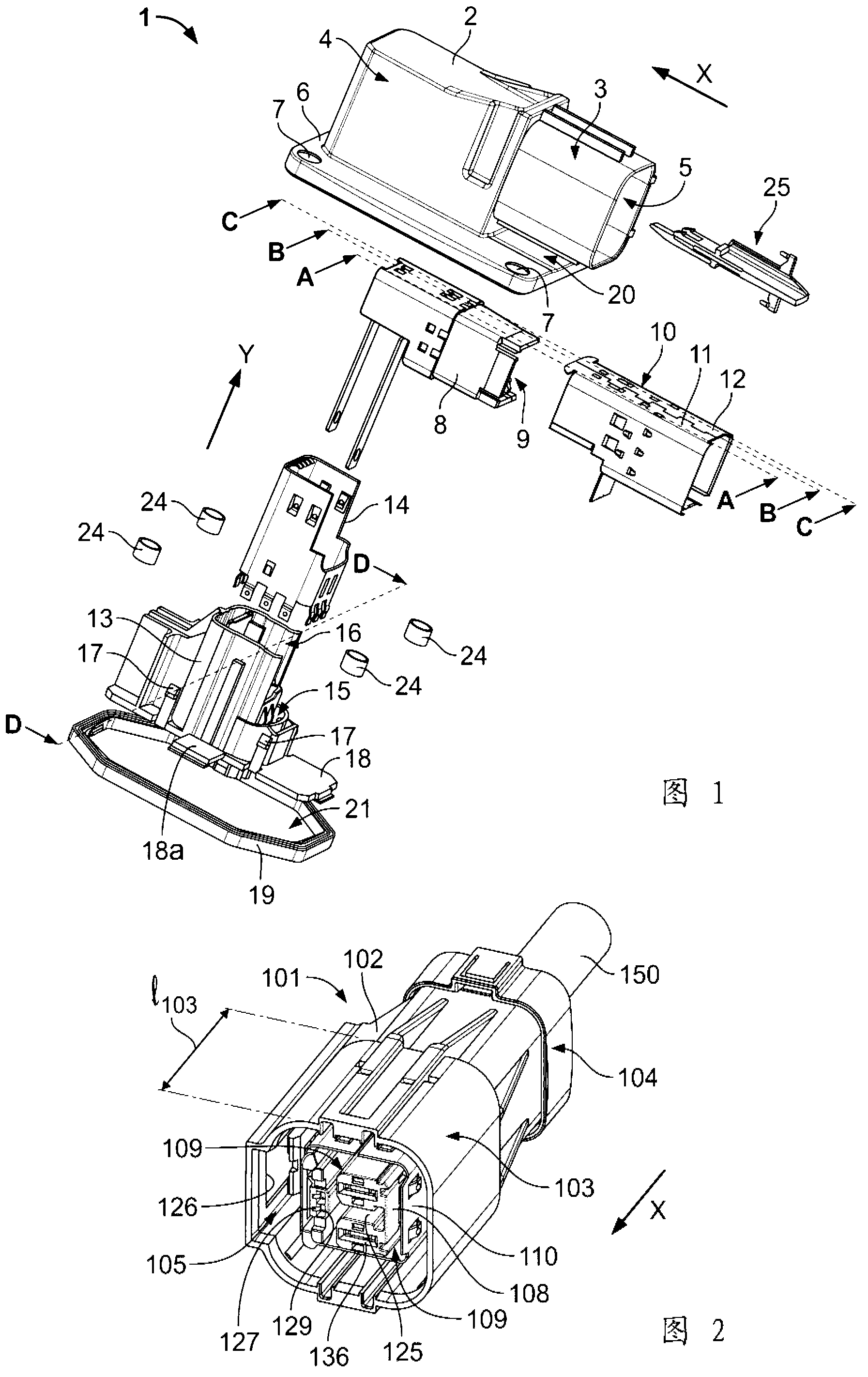
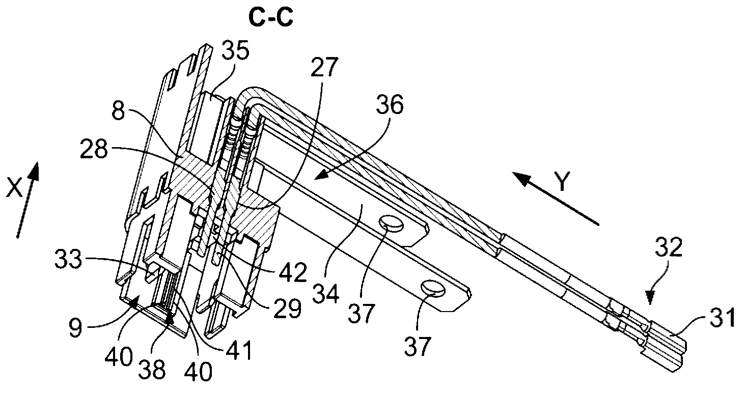
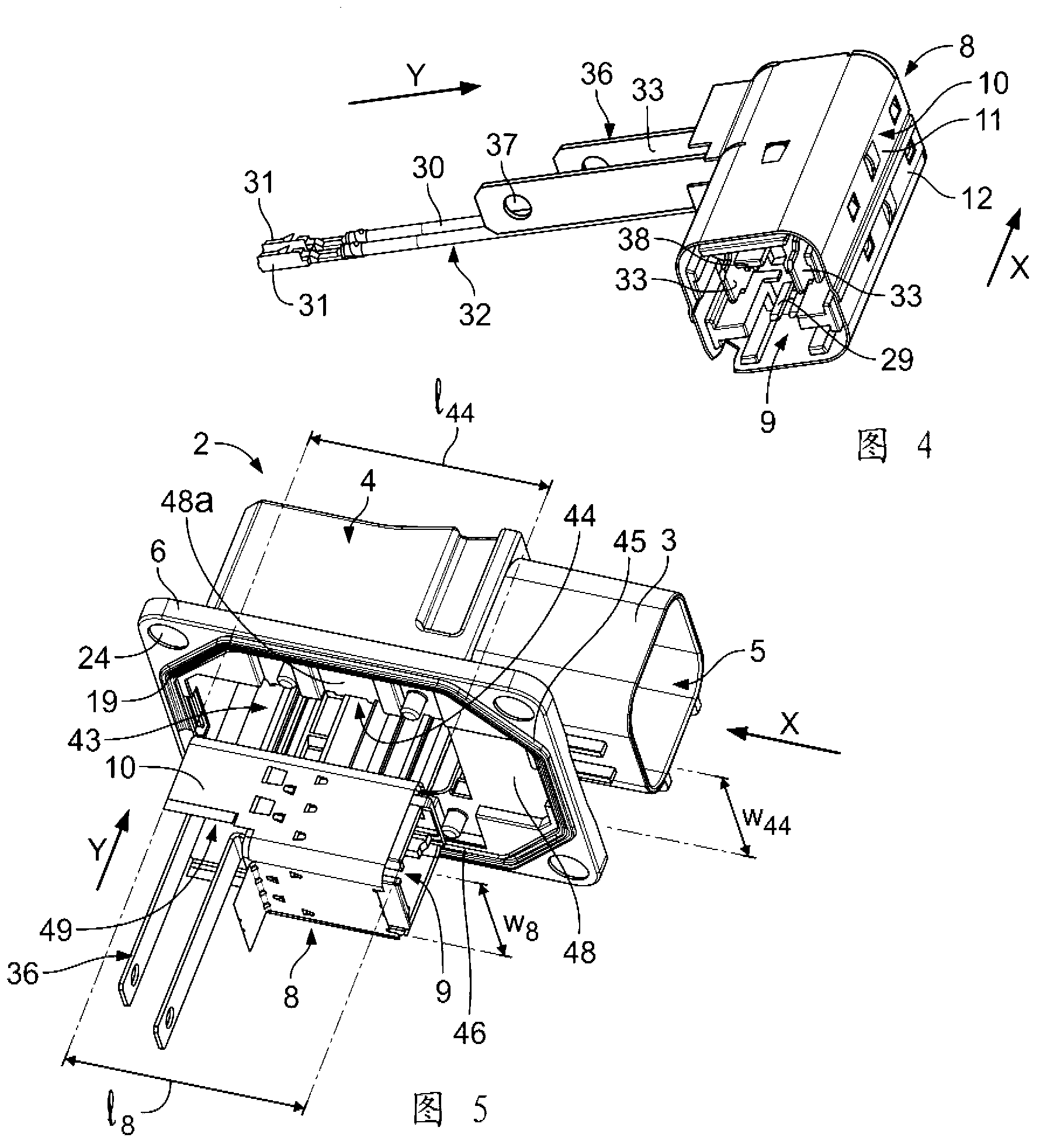
[0065] First, refer to figure 1 Description plug-in electrical connector 1, figure 1 The plug-in connector 1 is shown in an exploded perspective view. The plug-in connector 1 includes an outer body 2 having a plug part 3 and a mounting part 4. The plug part 3 has a plug opening 5 which opens in the plug-in direction X of the plug-in connector 1. The mounting portion 4 is used to mount the plug-in connector 1 to an electrical device, and is therefore provided with a base 6 having a mounting support 7 in the form of a through hole. The installation opening (not shown) of the outer body 2 and the installation support portion 7 are opened to the installation direction Y extending perpendicular to the insertion direction X.

[0066] The plug terminal housing 8 of the plug connector 1 has a plug surface 9. The insertion surface 9 of the plug terminal housing is open in the insertion direction X. The plug terminal housing 8 is arranged under the outer body 2 so as to be inserted into...


PUM


Abstract

The present invention relates to an electrical plug-in connector (1) in particular for high-voltage connections, comprising an outer body (2) having a plug opening (5) for receiving a mating plug-in connector (101), a terminal housing (8, 8', 8'', 13, 13', 13'', 13''') for fastening an electrical contact (36), and a finger protection member (25) projecting into the plug-in direction (X) towards the plug opening (5). Further, the present invention relates to a finger protection member (25) for an electrical high-voltage plug-in connector (1), with a bar-shaped body having a protection end (56), and to a construction kit for a high-voltage electrical plug-in connector (1), comprising an outer body (2) with a plug opening (5) for receiving a mating plug-in connector (101), and at least one terminal housing (8, 8', 8'', 13, 13', 13'', 13''') for fastening an electrical con- tact (36). Finally, the present invention relates to a method for assembling a plug-in connector (1), in particular for high-voltage connections, wherein a terminal housing (8, 8', 8'', 13, 13', 3'', 13''') of the plug-in connector (1) is inserted into an outer body (2) of the plug-in connector (1) having a plug opening (5) which opens towards a plug-in direction (X) of the plug-in connector (1). In order to provide a plug-in connector (1) which is more plug-compatible than 1 known connectors with a finger protection device (25), yet user friendly, the present invention provides that the finger protection member (25) is a separate piece engaged with the terminal housing (8, 8', 8'', 13, 13', 13'', 13''').

Description

Technical field [0001] The present invention relates to a plug-in electrical connector, especially for high-voltage connection. The plug-in electrical connector includes an outer body with a plug opening for receiving a mating plug-in connector ; A terminal housing for fastening the electrical contacts; and a finger protection member projecting in the plugging direction. [0002] Further, the present invention relates to a finger protection member for a high-voltage plug-in electrical connector, the finger protection member having a bar-shaped body with a protective end. [0003] In addition, the present invention relates to a structural kit for a high-voltage plug-in electrical connector, which includes: an outer body having a plug opening for receiving a mating plug-in connector; and at least one for fastening electrical contacts A terminal housing. [0004] Finally, the present invention relates to a method for assembling plug-in connectors, in particular for high-voltage connect...

Claims


Application Information

Patent Timeline
IPC IPC(8): H01R13/44H01R13/502H01R13/53H01R13/641
CPCH01R13/44H01R13/502H01R13/53H01R13/641H01R43/20H01R2201/26Y10T29/49208
Inventor M.埃克尔A.普拉奇奥F.阿梅里奥
Owner TYCO ELECTRONICS AMP ITAL
Learn More