Optical microphone

A microphone and optical technology, used in optical signal detection transducers, measuring devices, instruments, etc., can solve the problem of measuring devices becoming larger

Inactive Publication Date: 2013-06-12
PANASONIC CORP
View PDF2 Cites 7 Cited by
  • Summary
  • Abstract
  • Description
  • Claims
  • Application Information

AI Technical Summary

Problems solved by technology

Therefore, there is a problem that the entire measuring device disclosed in Patent Document 2 becomes large

Method used


Image

  • Optical microphone
  • Optical microphone
  • Optical microphone

Examples


no. 2 approach

[0165] Hereinafter, a second embodiment of the optical microphone according to the present invention will be described with reference to the drawings. In the optical microphone of Patent Document 1 or the method of Patent Document 2, although sound waves can be detected, the propagation direction of the sound waves cannot be determined, and the sound waves cannot be separated and detected according to frequencies. In contrast, the optical microphone of this embodiment can realize at least one of determining the propagation direction of the sound wave and separating and detecting the sound wave according to the frequency of the sound wave.

[0166] According to the optical microphone of this embodiment, at least one of the first interference light wave and the second interference light wave is detected using a photoelectric conversion element array including a plurality of photoelectric conversion elements. Therefore, the azimuths of these interfering light waves with respect t...

no. 3 approach

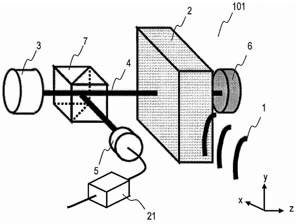
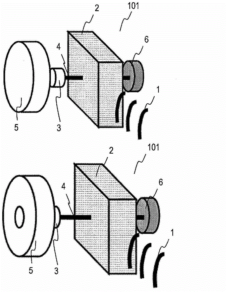
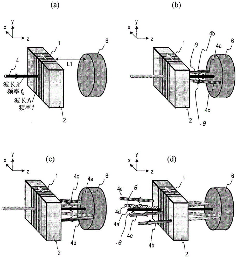
[0256] Figure 24 The structure of the main part of the optical microphone 103 of this embodiment is shown. The optical microphone 103 separates and detects the sound wave 1 according to its frequency using the light wave 4 . Therefore, the optical microphone 103 has the propagation medium section 2 , the light source 3 , the photoelectric conversion element array 26B, the reflection section 6 , the beam splitter 7 , and the light receiving lens system 15 . The configuration other than the photoelectric conversion element array 26B is the same as that of the optical microphone 102 of the second embodiment.

[0257] The photoelectric conversion element array 26B includes a plurality of photoelectric conversion elements 15 a , 15 b . . . 15 h. Each photoelectric conversion element has a plurality of ring-shaped light-receiving portions with different inner diameters and outer diameters, and the light-receiving portions are concentrically arranged around the position where the ...

no. 4 Embodiment approach

[0275] Figure 26 (a) shows the structure of the main part of the optical microphone 104 of this embodiment. The optical microphone 104 determines the propagation direction of the sound wave 1 using the light wave 4 , and separates and detects the sound wave 1 according to the frequency. To this end, the optical microphone 103 has a propagation medium section 2 , a light source 3 , a photoelectric conversion element array 26D, a reflection section 6 , a beam splitter 7 , and a light receiving lens system 15 . The configuration other than the photoelectric conversion element array 26D is the same as that of the optical microphone 102 of the first embodiment.

[0276] The photoelectric conversion element array 26D includes a plurality of photoelectric conversion elements 5a1, 5a2, ... 5a8, 5b1, 5b2, ... 5b8, ... 5x1, 5x2, ... 5x8. Each photoelectric conversion element has a partially ring-shaped light receiving portion, and the light receiving portion is two-dimensionally arra...


PUM


Abstract

An optical microphone is provided with a propagation medium unit through which an acoustic wave propagates, a light source which emits a light wave that crosses the acoustic wave propagating through the propagation medium unit and is transmitted through the propagation medium unit, a reflection unit which retroreflects the light wave transmitted through the propagation medium unit, and a photoelectric conversion unit which receives the light wave reflected by the reflection unit and transmitted through the propagation medium unit and outputs an electric signal. In an outward route in which the light wave emitted from the light source is transmitted through the propagation medium unit, a zero-order diffracted light wave, a positive first-order diffracted light wave, and a negative first-order diffracted light wave are each generated according to the refractive-index distribution of the propagation medium unit caused by the propagation of the acoustic wave, and in a return route in which the zero-order diffracted light wave generated in the outward route is transmitted through the propagation medium unit by being reflected by the reflection unit, a zero-order diffracted light wave, a positive first-order diffracted light wave, and a negative first-order diffracted light wave are generated according to the refractive-index distribution of the propagation medium unit caused by the propagation of the acoustic wave. The photoelectric conversion unit detects interference light between the positive first-order diffracted light wave generated in the outward route and the negative first-order diffracted light wave generated in the return route and / or interference light between the negative first-order diffracted light wave generated in the outward route and the positive first-order diffracted light wave generated in the return route.

Description

technical field [0001] The present application relates to an optical microphone that receives sound waves propagating in air and other gases, and uses light waves to convert the received sound waves into electrical signals. Background technique [0002] Microphones have long been known as devices that receive sound waves and convert them into electrical signals. Many microphones typified by dynamic microphones or condenser microphones have diaphragms. In these microphones, sound waves are received by vibrating a diaphragm, and the vibrations are taken out as electrical signals. Since this type of microphone has a mechanical vibrating part, the characteristics of the mechanical vibrating part may change after repeated use. Also, if you try to detect very strong sound waves with the microphone, you may damage the vibrator. [0003] In order to solve the problems of such conventional microphones having a mechanical vibrating portion, for example, Patent Document 1 and Patent...

Claims


Application Information

Patent Timeline
Patent Type & Authority Applications(China)
IPC IPC(8): G01H9/00H04R23/00
CPCH04R23/008G01H9/00
Inventor 岩本卓也桥本雅彦寒川潮金子由利子
Owner PANASONIC CORP
Why Eureka
Try Eureka