
Tensioning device comprising at least two ventilation elements

A technology of tensioning device and ventilation element, applied in the direction of transmission device, belt/chain/gear, mechanical equipment, etc., to achieve the effect of length increase

Inactive Publication Date: 2013-06-12
IWIS MOTORSYSTEME GMBH & CO KG
View PDF9 Cites 7 Cited by
  • Summary
  • Abstract
  • Description
  • Claims
  • Application Information

AI Technical Summary

Problems solved by technology

[0005] It is disadvantageous in known tensioning devices that only a certain area is available for the effective length of the throttle channel

Method used


Image

  • Tensioning device comprising at least two ventilation elements
  • Tensioning device comprising at least two ventilation elements
  • Tensioning device comprising at least two ventilation elements

Examples


Embodiment Construction

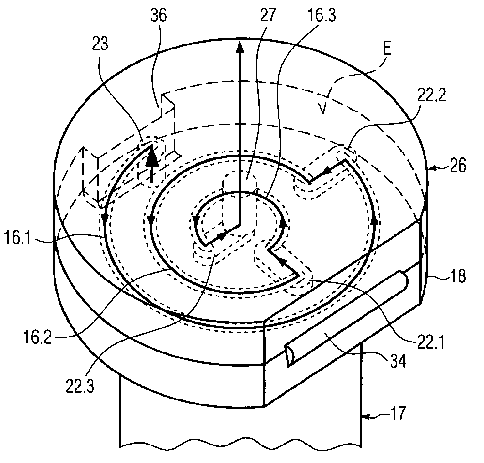
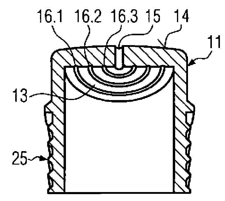
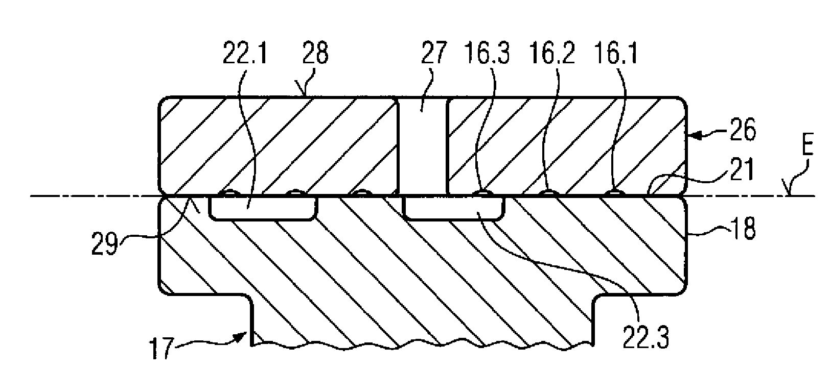
[0041] A control chain drive system 1 of an internal combustion engine is schematically shown in FIG. 1 . The control chain drive system 1 basically comprises a crankshaft sprocket 2, two upper camshaft sprockets 3 and 4, a control chain 5 wound around these sprockets, a slide rail 6, a pivotably arranged tensioning rail 7 and Tensioner 8 (or chain tensioner). For example, a screw-in chain tensioner 8 is shown, which is screwed into the region of the engine block housing 9 . The tensioning device 8 comprises a housing 10 and a tensioning piston 11 guided longitudinally displaceably in the housing 10 . The tensioning device 8 is coupled to the engine oil hydraulic transmission system, so that the hydraulic oil flows into the interior of the tensioner housing 10 through a feed hole (not shown) and acts on the tensioning piston 11 with pressure so that it presses against The tensioning rail 7 is pivotably arranged so that it bears against the control chain 5 under pretension. ...


PUM


Abstract

The invention relates to a tensioning device (8) for an endless drive element, in particular a timing chain (5) of an internal combustion engine, comprising a housing (10), a tensioning piston (11) which can be movably guided in the housing (10), and a pressure chamber (19) for a hydraulic fluid, formed between the housing (10) and the tensioning piston (11), wherein the tensioning piston (11) has a ventilation opening (15) and a ventilation channel (23, 16.1, 16.2, 16.3, 22.1, 22.2, 22.3) is provided which is disposed between the pressure chamber (19) and the ventilation opening (15) and which is formed by the assembly of at least two ventilation elements. In one ventilation element, in the surface (E) which contacts the second ventilation element, sub-regions of the ventilation channel which are separated from one another are formed by indented groove sections (16.1, 16.2, 16.3, 22.1, 22.2, 22.3), which are connected to one another by transitional grooves (22.1, 22.2, 22.3) formed in the second ventilation element in the surface which contacts the first ventilation element in such a way that a main part of the flow cross-section of the ventilation channel is disposed with some sections on one side and some sections on the other side of a plane spanned by the contact surfaces. The invention further relates to a corresponding traction drive (1) having such a tensioning device (8).

Description

technical field [0001] The invention relates to a tensioning device for an endless transmission element (Endlostreibelement), in particular a control chain (Stuerkette, sometimes also called a timing chain) of an internal combustion engine, which has a housing and is displaceably guided in the housing A tensioning piston and a pressure chamber for hydraulic fluid configured between the casing and the tensioning piston, wherein the tensioning piston has a ventilation hole and is provided with a ventilation channel arranged between the pressure chamber and the ventilation hole, which Formed (ausformed) by combining at least two ventilation elements. Background technique [0002] Such a tensioning device is known, for example, from document DE 4431161 A1. The tensioning device is primarily used for tensioning the control chain of a control chain drive system on an internal combustion engine. The tensioning piston presses against a pivotably arranged tensioning rail which pres...

Claims


Application Information

Patent Timeline
Patent Type & Authority Applications(China)
IPC IPC(8): F16H7/08
CPCF16H7/0836F16H2007/0806F16H2007/0817F16H2007/0859F16H7/08
Inventor C.鲍尔T.施密德
Owner IWIS MOTORSYSTEME GMBH & CO KG
Learn More