
Optical frequency comb generator based on time-frequency mapping

An optical frequency comb and generator technology, applied in the field of microwave photons, can solve the problem that the output spectrum performance is difficult to be further improved.

Inactive Publication Date: 2013-06-12
BEIHANG UNIV
View PDF2 Cites 17 Cited by
  • Summary
  • Abstract
  • Description
  • Claims
  • Application Information

AI Technical Summary

Problems solved by technology

The former needs to build a complex structure similar to a laser, and its output spectrum is easily affected by the external temperature and the loss characteristics of materials such as optical fibers. It is difficult to further improve the performance.

Method used


Image

  • Optical frequency comb generator based on time-frequency mapping
  • Optical frequency comb generator based on time-frequency mapping
  • Optical frequency comb generator based on time-frequency mapping

Examples


Embodiment Construction

[0042] specific implementation

[0043] The performance of the optical frequency comb generator proposed by the present invention has been verified by experiments, and the experimental device is as figure 1 As shown, the experimental process and experimental results are described below in conjunction with the accompanying drawings.

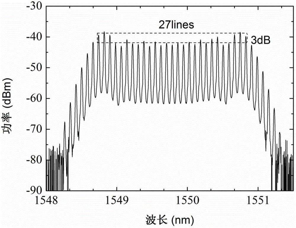
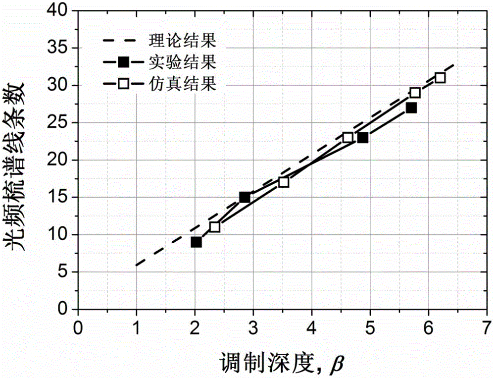
[0044] like figure 1 As shown, first set the bias of the intensity modulator at the quadrature bias point, and work in the linear modulation region, that is, set its parameters to α=0.5, γ=-0.5 respectively. The modulation signal of the intensity modulator and the phase modulator is a 10GHz radio frequency signal, and the continuous wave output by the laser is modulated by the intensity modulator to output a flat top optical pulse. Then by changing the modulation depth of the phase modulator to obtain different numbers of output spectral lines. When the modulation depth β=5.71, the experiment obtained 27 spectral lines with a flatness of 3dB, s...


PUM


Abstract

The invention discloses a generating device for generating an optical frequency comb based on time-frequency mapping and a method for estimating the number of output optical frequency comb lines. Experiment devices are shown as in the picture, and the experimental method specifically comprises the following steps: setting an intensity modulator to have an orthogonal offset and work in a linear offset area, and outputting a flat light pulse after the intensity modulation of continuous lightwaves; and applying chromatic dispersion optical fibers and an optical phase modulator to map the time-domain flat light pulse to a frequency-domain flat optical frequency comb. The obtained number of the optical frequency comb lines can be estimated according to the time-domain width of the flat light pulse and the modulation depth of the phase modulator. Compared with the existing scheme, the scheme is utilized to obtain more accurate time frequency mapping through introducing the chromatic dispersion optical fibers.

Description

technical field [0001] The cascaded optical intensity modulation and phase modulation based on radio frequency signals can generate optical frequency combs, or optical frequency combs. In order to obtain as many flat spectral lines as possible, it is usually necessary to rationally optimize the DC bias point of the intensity modulator and the modulation depth of the intensity modulator and phase modulator. The invention relates to a generating device for generating an optical frequency comb by optical modulation, which can realize the mapping from flat-top waveforms in time domain to flat spectral lines in frequency domain by disposing a certain length of dispersion optical fiber between an intensity modulator and a phase modulator , where the optical intensity modulator needs to be reasonably configured to output a flat-top waveform without parameter optimization, and the number of spectral lines of the output optical frequency comb can be estimated according to the width of ...

Claims


Application Information

Patent Timeline
IPC IPC(8): G02F1/37H01S3/109
Inventor 闫娟娟彭亦超
Owner BEIHANG UNIV
Learn More