
Steel ring beam structure of steel plate silo

A beam structure and silo technology, applied in the field of steel ring beam structure, can solve the problems of high welding technology requirements, bulky steel ring beam structure, reduced welding strength, etc., to reduce the difficulty of installation and construction, stable and reliable structure, and convenient The effect of making and installing

Active Publication Date: 2013-06-12
安阳市大正钢板仓有限责任公司
View PDF6 Cites 4 Cited by
  • Summary
  • Abstract
  • Description
  • Claims
  • Application Information

AI Technical Summary

Problems solved by technology

At present, the steel plate silos that have been built are mostly supported by steel columns according to the owner’s requirements, based on the principle of simplicity, speed, and small investment. The structure of the steel ring beam is relatively bulky and requires high welding technology. The last welding connection surface can only be welded outside the steel ring beam, so that the plates that should have been welded on both sides can only be welded on one side, which greatly reduces the welding cost. strength

Method used


Image

  • Steel ring beam structure of steel plate silo

Examples


Embodiment Construction

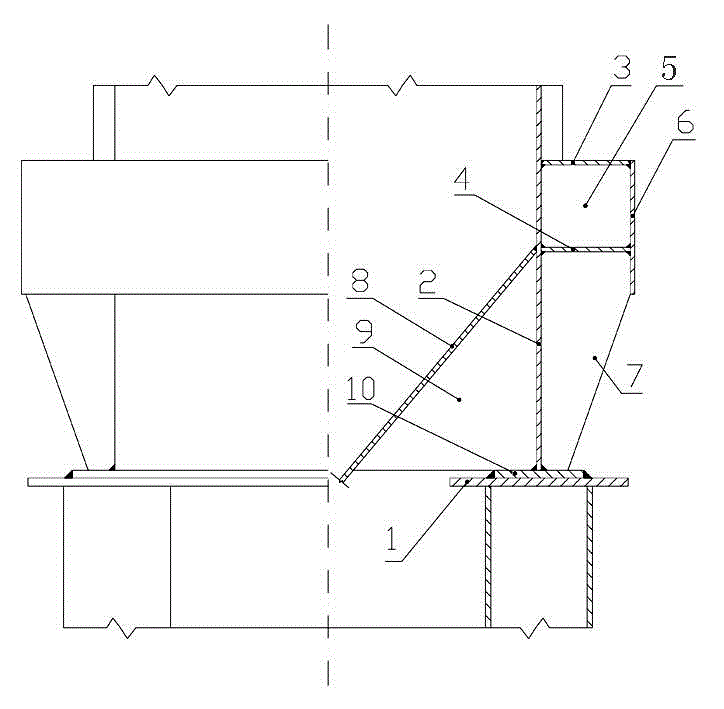
[0008] Such as figure 1 As shown, the steel ring beam structure of the steel plate silo of the present invention includes an annular backing plate 10 welded on the upper surface of the supporting steel column top plate 1, and a silo 2 whose bottom edge is welded on the upper surface of the annular backing plate 10. The outer peripheral surface of the silo 2 is welded with upper and lower annular reinforcing plates 3 and 4 at intervals, and the height of the lower annular reinforcing plate 4 is equal to the upper edge of the conical lower hopper arranged in the silo 2; Between the lower annular reinforcement plates 3 and 4, a plurality of vertical plates 5 are uniformly welded at radial intervals, and the outer edges of the upper and lower annular reinforcement plates 3 and 4 are welded with annular vertical plates 6, and the annular vertical plates 6 The lower edge of the lower edge extends to below the lower annular reinforcing plate 4; a plurality of reinforcing vertical pla...


PUM


Abstract

The invention discloses a steel ring beam structure of a steel plate silo. The steel ring beam structure comprises the silo fixed on a support steel column top plate, wherein an annular base plate is welded on the support steel column top plate; a bottom edge of the silo is welded with the annular base plate; an upper annular reinforcing plate and a lower annular reinforcing plate are sleeved and welded on an outer circumference of the silo at an interval; a plurality of vertical plates are welded between the upper annular reinforcing plate and the lower annular reinforcing plate along a radial direction at intervals; annular vertical plates are sleeved and welded on outer edges of the upper annular reinforcing plate and the lower annular reinforcing plate; lower edges of the annular vertical plates are extended to a lower part of the lower annular reinforcing plate; a plurality of reinforcing vertical plates are uniformly distributed and welded on a lower surface of the lower annular reinforcing plate along a radial direction; the lower end of each reinforcing vertical plate is respectively welded with the annular base plate; and a plurality of support connecting vertical plates are uniformly distributed and welded along a radial direction at intervals in an area surrounded by a side wall of a conical lower hopper in the silo, the annular base plate and the side wall of the silo. According to the steel ring beam structure of the steel plate silo, the difficulty in installation and construction of the annular lower hopper of the steel plate silo is reduced, and the structure of the steel plate silo is simpler and more practical, and is convenient to manufacture and install.

Description

technical field [0001] The invention relates to a steel plate silo, in particular to a steel ring beam structure of the steel plate silo. Background technique [0002] Steel silos are mainly used to store bulk materials, such as agricultural silos used to store granular and powdery materials such as grain and feed, and industrial silos used to store bulk materials such as coke, cement, salt, and sugar. At present, the steel plate silos that have been built are mostly supported by steel columns according to the owner’s requirements, based on the principle of simplicity, speed, and small investment. The structure of the steel ring beam is relatively bulky and requires high welding technology. The last welding connection surface can only be welded outside the steel ring beam, so that the plates that should have been welded on both sides can only be welded on one side, which greatly reduces the welding cost. strength. Contents of the invention [0003] The object of the pres...

Claims


Application Information

Patent Timeline
Patent Type & Authority Applications(China)
IPC IPC(8): E04H7/30
Inventor 周彬郑强张太平翟兰军
Owner 安阳市大正钢板仓有限责任公司
Learn More