Suction device on spinning machine
A technology for suction equipment and spinning machines, applied in spinning machines, drafting equipment, textiles and papermaking, etc., can solve expensive and complicated problems, achieve firm connection, reduce frictional resistance, simple and detachable connection Effect
Active Publication Date: 2017-09-15
MASCHINENFABRIK RIETER AG
View PDF2 Cites 0 Cited by
- Summary
- Abstract
- Description
- Claims
- Application Information
AI Technical Summary
Problems solved by technology
In order to be able to use the injection molding method to produce collector pipes with attached suction pipes according to DE 101 44 570 A1, complex and expensive injection molding tools are necessary
Method used
View moreImage
Smart ImageViewing Examples

Examples
Embodiment Construction
Login to View More PUM
 Abstract
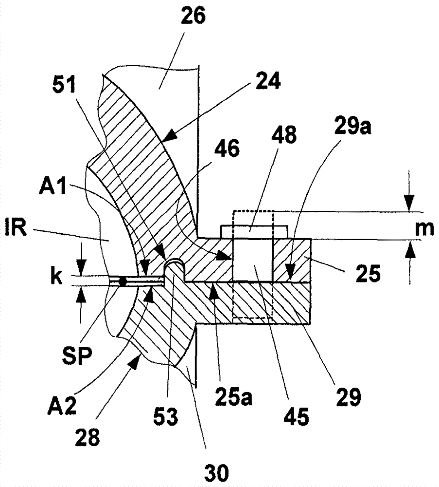
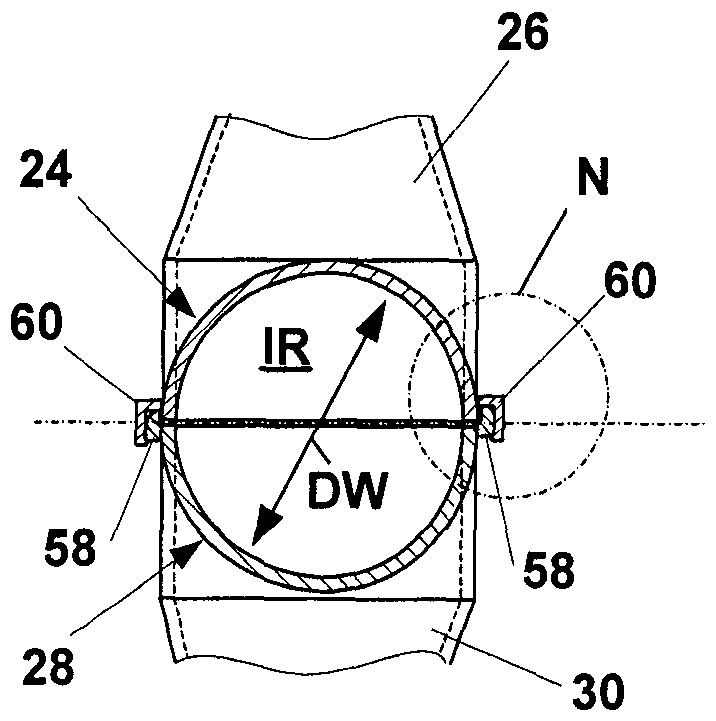
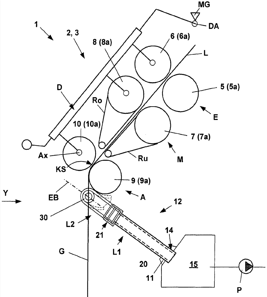
The invention relates to a suction device on a spinning machine. A suction device for two drafting device units (2, 3) arranged next to each other of a spinning machine, comprising a collector pipe (12) and a two suction ducts (26, 30), the two outwardly directed openings (17, 18) of the two suction ducts are directed with respect to the yarn (G) delivered from the respective drafting device unit (2, 3), Wherein the ends of the suction pipes opposite the outer openings (17, 18) lead through the inner openings (32, 33) to the common collector pipe (12). In order to simplify the production of the known suction devices and to avoid clogging, it is proposed that the outwardly pointing openings (17, 18) of the suction pipes (26, 30) point in opposite directions and that the suction to the collector pipe (12) The openings ( 32 , 33 ) of the straws are coaxially opposite each other.
Description
Suction device on spinning machine Technical field The present invention relates to a suction device for two drafting device units arranged next to each other of a spinning machine, comprising a collector tube and two suction devices extending from the collector tube and extending in opposite directions. The suction tube, and the outwardly directed openings of the two suction tubes point to the yarn delivered from each drafting device unit, wherein the ends of the two suction tubes opposite to the outer opening lead to the common collector tube through the inner opening. Background technique A particular problem with spinning machines is that in the event of a thread break, the fibrous material still conveyed from the drafting device unit must be conveyed away so that it does not enter the spinning element in an uncontrolled manner. For this purpose, suction devices are used, in which for each spinning station, a suction pipe is arranged near the flow of fiber material. Such ...
Claims
Login to View More Application Information
Patent Timeline
 Patent Type & Authority Patents(China)
IPC IPC(8): D01H5/68
Inventor R.纳格利G.施奈德
Owner MASCHINENFABRIK RIETER AG
Features
- R&D
- Intellectual Property
- Life Sciences
- Materials
- Tech Scout
- Unparalleled Data Quality
- Higher Quality Content
- 60% Fewer Hallucinations
Learn More Browse by: Latest US Patents, China's latest patents, Technical Efficacy Thesaurus, Application Domain, Technology Topic, Popular Technical Reports.
© 2025 PatSnap. All rights reserved.Legal|Privacy policy|Modern Slavery Act Transparency Statement|Sitemap|About US| Contact US: help@patsnap.com