Buoyant piston
A buoyancy and engine technology, applied in hydroelectric power generation, mechanisms for generating mechanical power, engine components, etc., can solve problems such as supply crisis, high price, and aggravation, and achieve the effect of smooth power output, no pollution, and high efficiency
- Summary
- Abstract
- Description
- Claims
- Application Information
AI Technical Summary
Problems solved by technology
Method used
Image
Examples
Embodiment 1
[0025] Embodiment 1: spring compression upper power output mode
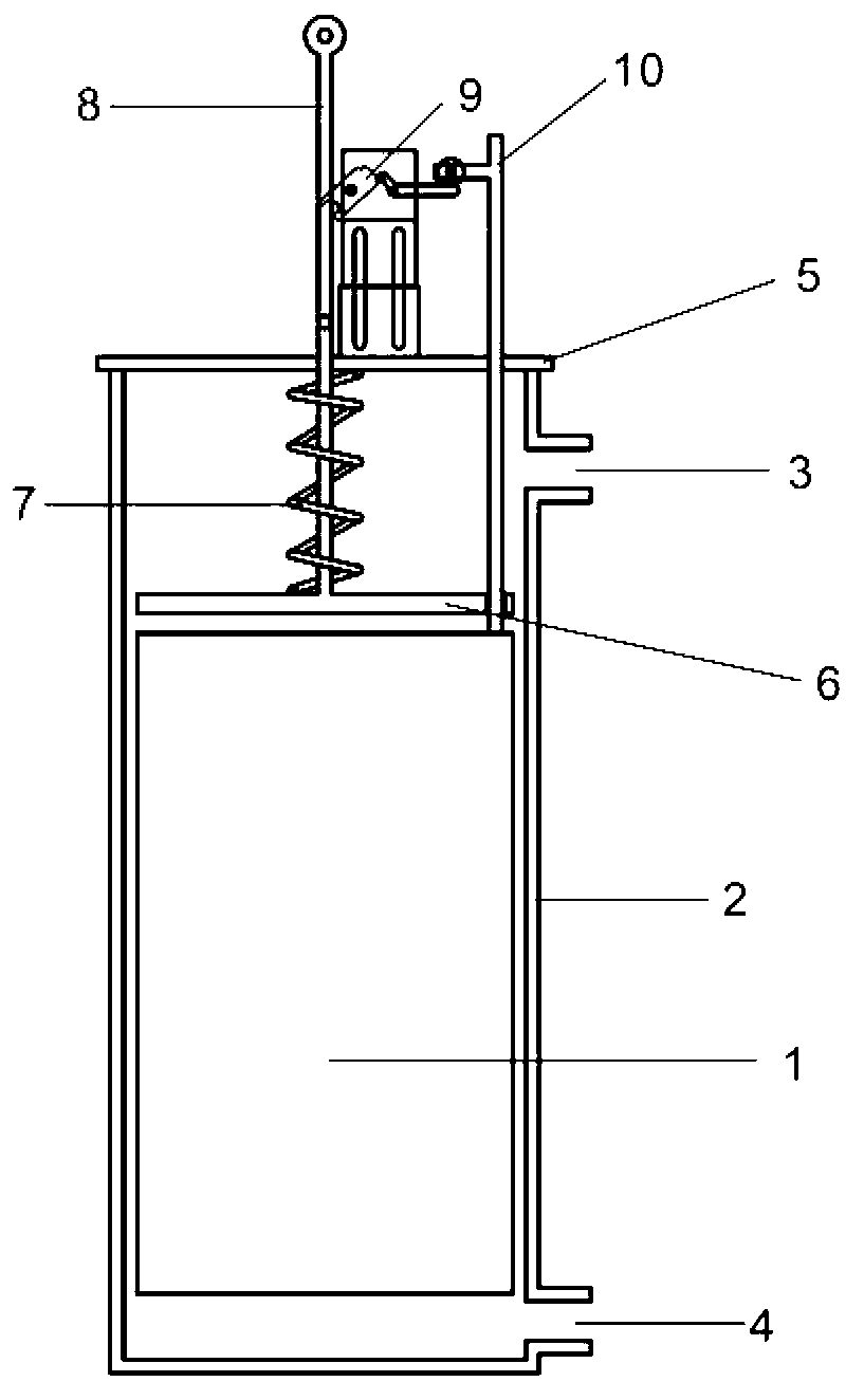
[0026] Such as figure 1 As shown, the present embodiment includes a buoyancy piston 1, a piston cylinder 2 matched with the buoyancy piston 1, the upper part of the piston cylinder 2 is provided with a water inlet 3, and the lower part is provided with a water outlet 4; the piston cylinder 2 also has a piston Cylinder head 5. The energy storage mechanism above the buoyancy piston 1 is a spring type, including a pressure spring 7 and a buoyancy compression disk 6 , and the spring 7 is placed between the piston cylinder head 5 and the buoyancy compression disk 6 . The lower end of the power take-off rod 8 is fixed in the center of the buoyancy compression disc 6, passes through the center of the spring 7 and is drawn out through the opening in the center of the piston cylinder head 5, can rise under the action of buoyancy, and descend under the action of the spring 7. The power take-off rod 8 can be fixed by the...
Embodiment 2
[0027] Embodiment 2: Power output mode under spring compression
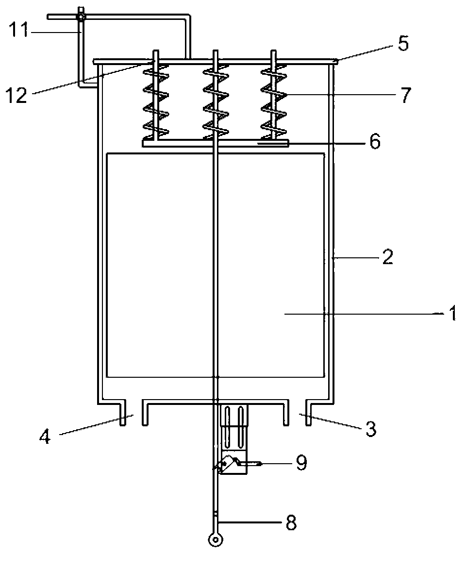
[0028] Such as figure 2 As shown, this embodiment is a large-scale buoyancy engine, including a buoyancy piston 1, a piston cylinder 2 matched with the buoyancy piston 1, and the water inlet 3 and the water outlet 4 of the piston cylinder 2 are all opened at the bottom of the piston cylinder There is also a piston cylinder cover 5 on the piston cylinder body 2, and an automatic cover opener 11 has also been increased on the piston cylinder cover 5, and its form is mechanical, electric, hydraulic or hanging. The energy storage mechanism above the buoyancy piston 1 is a spring type, comprising a group of springs 7 and a buoyancy compression disk 6, the spring group 7 is placed between the piston cylinder cover 5 and the buoyancy compression disk 6, and a guide rod 12 is arranged at the center, the said The lower part of the guide rod 12 is fixed on the buoyancy compression disc 6, and the upper part stretches ou...
Embodiment 3
[0029] Embodiment 3: Power rotation output mode under spring compression
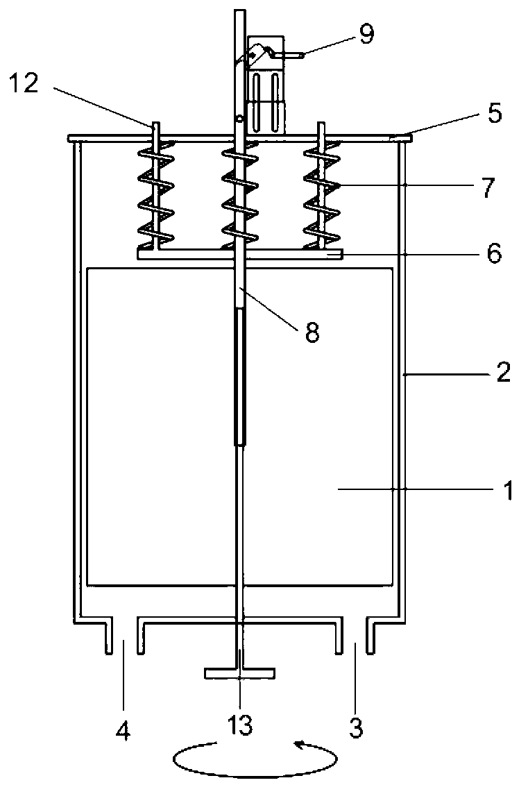
[0030] Such as image 3 As shown, the present embodiment includes a buoyancy piston 1, a piston cylinder 2 matched with the buoyancy piston 1, the water inlet 3 and the water outlet 4 of the piston cylinder 2 are all opened at the bottom of the piston cylinder; There is also the piston cylinder cover 5, the energy storage mechanism above the buoyancy piston 1 is a spring type, including one group of springs 7 and the buoyancy compression disc 6, the spring group 7 is placed between the piston cylinder cover 5 and the buoyancy compression disc 6, and the center is set A guide rod 12 is arranged, and the lower part of the guide rod 12 is fixed on the buoyancy compression disc 6, and the upper part stretches out from the piston cylinder cover 5. The power take-off rod 8 is drawn from the opening at the center of the bottom of the piston cylinder 2, and its middle part is fixedly connected to the center of...
PUM
 Abstract
Description
Claims
Application Information
 - R&D
- Intellectual Property
- Life Sciences
- Materials
- Tech Scout
- Unparalleled Data Quality
- Higher Quality Content
- 60% Fewer Hallucinations
Browse by: Latest US Patents, China's latest patents, Technical Efficacy Thesaurus, Application Domain, Technology Topic, Popular Technical Reports.
© 2025 PatSnap. All rights reserved.Legal|Privacy policy|Modern Slavery Act Transparency Statement|Sitemap|About US| Contact US: help@patsnap.com


