
Modulation method of low sidelobe random frequency hopping pulse signal

A technology of pulse signal and modulation method, which is applied in the modulation field of frequency hopping pulse signal, can solve the problems of poor precision optimization ability, slow convergence speed, slow modulation speed of random frequency hopping pulse signal, etc., and achieve accurate local precision optimization ability , improved convergence speed, time-consuming and time-saving effects of random frequency hopping pulse signal modulation

Inactive Publication Date: 2013-06-05
HARBIN INST OF TECH
View PDF4 Cites 12 Cited by
  • Summary
  • Abstract
  • Description
  • Claims
  • Application Information

AI Technical Summary

Problems solved by technology

[0004] In order to solve the problem that the traditional low side lobe random frequency hopping pulse signal modulation method has poor local accurate optimization ability and slow convergence speed, which leads to slow modulation speed of random frequency hopping pulse signal, a low side lobe random frequency hopping pulse signal modulation method is proposed. Modulation method of frequency pulse signal

Method used


Image

  • Modulation method of low sidelobe random frequency hopping pulse signal
  • Modulation method of low sidelobe random frequency hopping pulse signal
  • Modulation method of low sidelobe random frequency hopping pulse signal

Examples


specific Embodiment approach 1

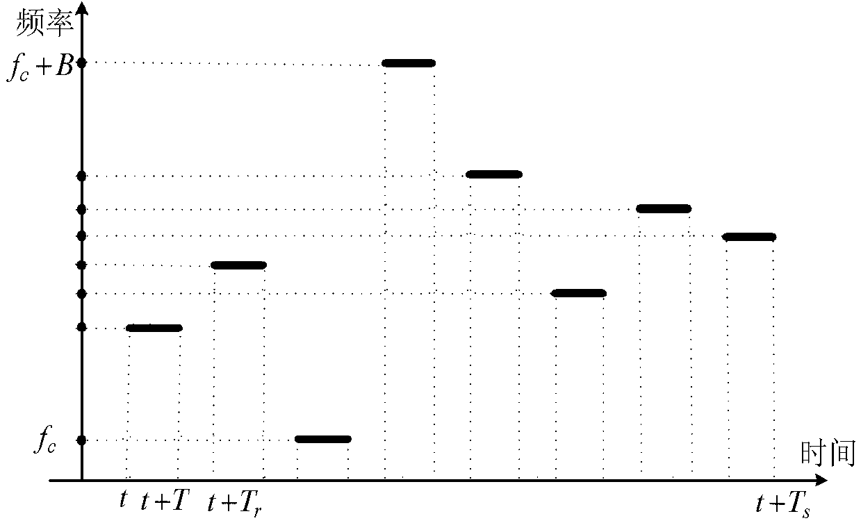
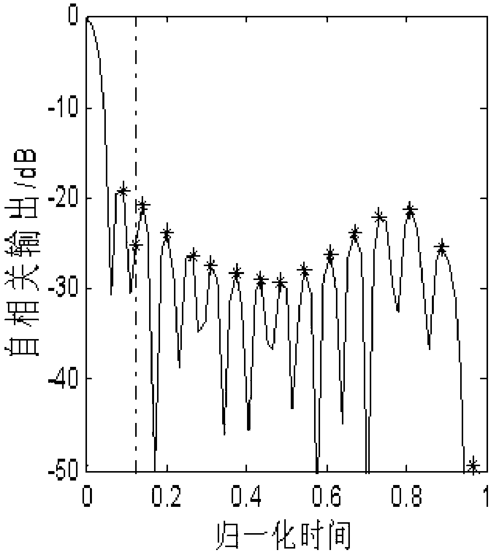
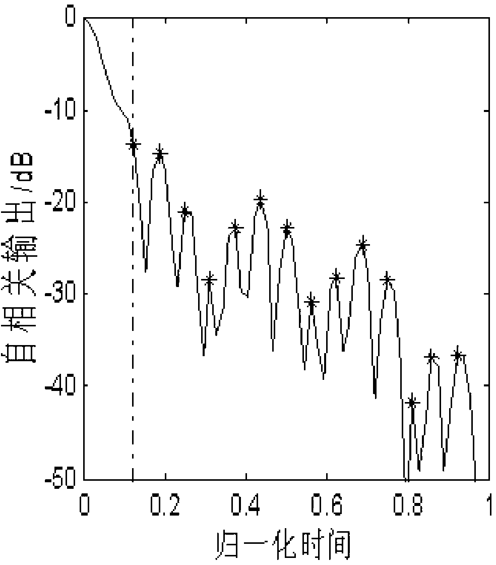
[0038] Specific implementation mode 1. Combination figure 1 , figure 2 , image 3 , Figure 4 , Figure 5 and Figure 6 Describe this embodiment, the specific steps of the modulation method of a low sidelobe random frequency hopping pulse signal described in this embodiment:

[0039] A kind of modulation method of low side lobe random frequency hopping pulse signal, it is characterized in that, its modulation method is realized by the following steps:

[0040] Step 1, the random frequency hopping pulse signal s(t) to be modulated is according to the formula:

[0041] χ ( τ ) = 1 N 2 ( 1 - | τ | T ) 2 Σ ...

specific Embodiment approach 2

[0064] Specific embodiment two, this embodiment is a further description of the modulation method of a low-sidelobe random frequency-hopping pulse signal described in specific embodiment one, and the maximum value of the deviation function E (τ) described in step eight corresponds to time τ i,max According to the gradient principle, the frequency combination is adjusted for a stage, and the method for obtaining a group of adjusted frequency combinations is as follows:

[0065] Step A, the time τ corresponding to the maximum value of the deviation function E(τ) i,max , according to the formula:

[0066] Δ f i , j = - η dE ( τ i ...


PUM


Abstract

The invention provides a modulation method of a low sidelobe random frequency hopping pulse signal, relates to the modulation method of a frequency hopping pulse signal and solves the problems existing in a traditional modulation method of the low sidelobe random frequency hopping pulse signal that local accuracy optimization ability is bad, the modulation speed of the random frequency hopping pulse signal is low caused by low convergence speed. According to the modulation method of the low sidelobe random frequency hopping pulse, a self-correlation function of the random frequency hopping pulse signal is derived, the self-correlation function is used to calculate a deviation function of the random frequency hopping pulse signal and calculate an initialization frequency combination, the initialization frequency combination is brought into the deviation function to obtain an optimal frequency combination, stochastic disturbance is added, and the deviation function is updated. The updated deviation function is detected, a moment corresponding to the maximum value point of the deviation function is used, according to a gradient theory, the frequency combination is conducted with a-stage frequency adjustment, until a difference value of deviation functions of two adjacent stages is smaller than a set threshold, the frequency combination update is stopped, and the random frequency hopping pulse signal modulation is completed. The modulation method of the low sidelobe random frequency hopping pulse signal is applicable to the field of signal modulation.

Description

technical field [0001] The invention relates to a modulation method of a frequency-hopping pulse signal. Background technique [0002] Radar obtains its space and motion information by analyzing the target's echo. In order to obtain a more accurate distance estimate for the target, it usually needs to transmit a signal with a larger bandwidth. The frequency-stepped pulse signal has a large resolution bandwidth obtained by synthesizing multiple narrow-band pulses, and the frequency interval between the pulses is uniform. Due to the convenience of generation and processing, the frequency-stepped pulse signal has been widely used in high-resolution distance imaging. However, the first range sidelobe of the stepped frequency pulse signal is relatively high, about -13dB, which has a negative impact on the detection of weak targets. In addition, in order to avoid periodic ambiguous grating lobes, the parameter restriction that the product of frequency step quantization interval a...

Claims


Application Information

Patent Timeline
Patent Type & Authority Applications(China)
IPC IPC(8): H04B1/7176G01S7/282
Inventor 位寅生赵德华邓维波
Owner HARBIN INST OF TECH
Learn More