
Air spring for moving body and moving body vehicle using the air spring

An air spring and moving body technology, applied in the field of air springs, can solve the problems of complex structure and increased cost, and achieve the effect of simple structure

Active Publication Date: 2015-08-12
SUMITOMO ELECTRIC IND LTD
View PDF10 Cites 0 Cited by
  • Summary
  • Abstract
  • Description
  • Claims
  • Application Information

AI Technical Summary

Problems solved by technology

[0007] According to the structure of Patent Document 1, it is possible to maintain the ride comfort when the air is deflated, and to suppress the derailment coefficient of the vehicle to be low, thereby ensuring the running stability, but the structure becomes complicated, which becomes a factor of cost increase
In addition, the structure of Patent Document 2 is a structure that utilizes the nonlinear spring characteristics, reduces the influence on ride comfort, and limits the amount of sinking of the vehicle body, thereby enabling safe driving. However, it is necessary to use a plurality of stopper rubbers.

Method used


Image

  • Air spring for moving body and moving body vehicle using the air spring
  • Air spring for moving body and moving body vehicle using the air spring
  • Air spring for moving body and moving body vehicle using the air spring

Examples


Embodiment Construction

[0045] The structure of the air spring according to the present invention will be described with reference to the drawings. In addition, elements marked with the same reference numerals in different drawings represent the same or corresponding elements. The present invention is not limited to these configurations but is shown by the claims, and includes the same contents as the claims and all modifications within the scope thereof.

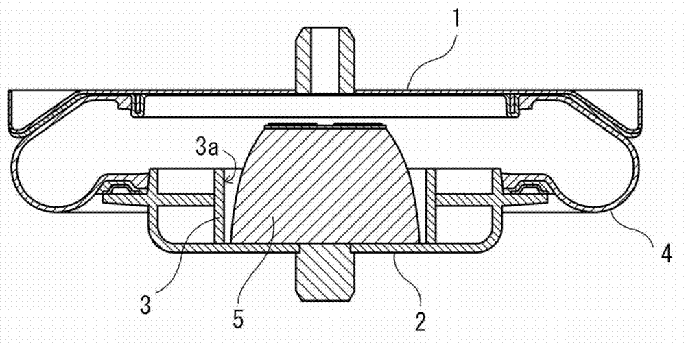
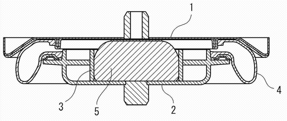
[0046] figure 1 It is a schematic cross-sectional view showing an air spring as an example of the present invention. figure 1 Shows a cross section of the air spring cut along a vertical plane passing through its central axis, and does not show a plan view or a bottom view, but the overall shape is a circular shape rotated around the central axis. use figure 1 The basic structural elements of the present invention and their functions will be described. The basic structure of the air spring is composed of a diaphragm 4, and the upper and lower ...


PUM


Abstract

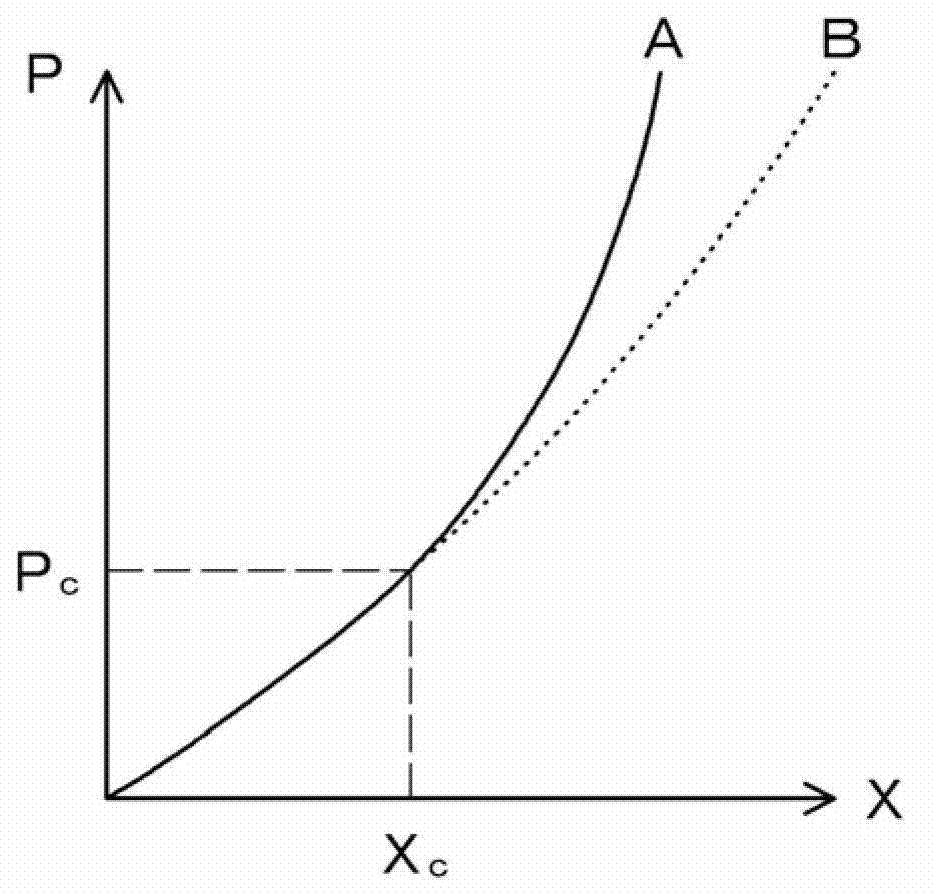
The invention discloses an air spring for a moving body. The air spring for a moving body is characterized by simple structure and realization of riding comfort and vehicle running stability. The air spring for a moving body is provided with a diaphragm, a stopping rubber, and a suppressing face part, wherein the diaphragm is clamped by an upper face plate and a lower face plate, the upper face plate is arranged at a vehicle side, the lower face plate is arranged at a bogie side, the stopping rubber is arranged between the upper face plate and the lower face plate, and the suppressing face part is provided with a suppressing face which is opposite to a side face of the stopping rubber. The air spring for the moving body is characterized in that in air discharging processes, the contact area between the side face of the stopping rubber and the suppressing face correspondingly varies along with the stopping rubber shape changes corresponding to changes of a load applied on the stopping rubber.

Description

technical field [0001] The present invention relates to an air spring used for moving bodies such as railway vehicles, and in particular, to an air spring with improved running safety at the time of deflation (explosion). Background technique [0002] Air springs are used as springs between the car body and the bogie of railway vehicles because they improve the ride comfort of the moving body and keep the step between the car body and the platform constant regardless of the number of passengers. Since the air spring uses a diaphragm that expands with air, it is generally excellent in terms of ride comfort during driving, but when deflated, air leaks out and the diaphragm does not function. Therefore, for the purpose of improving ride comfort during air deflation or preventing derailment of a railway vehicle, a structure is adopted in which a stopper rubber (inner stopper) is provided inside the diaphragm. [0003] Patent Document 1 discloses an air spring having the above-m...

Claims


Application Information

Patent Timeline
Patent Type & Authority Patents(China)
IPC IPC(8): B61F5/10F16F9/05
Inventor 泽隆之
Owner SUMITOMO ELECTRIC IND LTD
Learn More