


Quick Research
Generate reliable direction feasibility study reports for your R&D in just a few steps.

Technical Q&A
Discover and master advanced knowledge NOW. Basics, ideas, possibilities, all at once.

Find Solutions
As an expert in R&D theories, this can generate solutions to your technical problems instantly.

Evaluate Feasibility
Analyze your overall solution with one click, know your potential R&D risks in advance.

Monitor Landscape
Get weekly tech updates, stay abreast of the latest tech innovations and key insights.
Paper membrane compound product cutting device and cutting method
A paper film and cutting technology, applied in the direction of chemical instruments and methods, layered products, lamination auxiliary operations, etc., can solve the problems affecting the production efficiency of the laminating equipment production line, the quality of the blade, the sharpness requirements are very high, and the increase of laminating Production costs and other issues, to achieve the effect of ingenious structure, low specification requirements, high cutting quality
- Summary
- Abstract
- Description
- Claims
- Application Information
AI Technical Summary
Problems solved by technology
Method used
Image

Examples
Embodiment 1
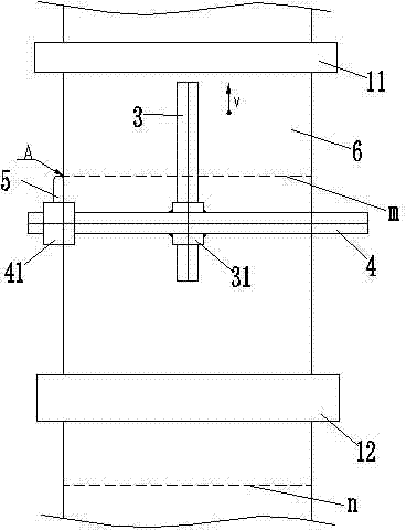
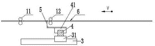
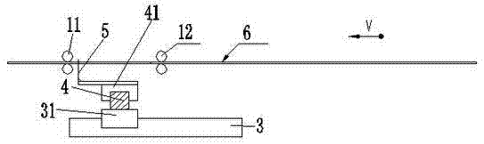
[0036] figure 1 , figure 2 , image 3 As shown, the paper film composite cutting equipment includes a pair of nip rollers 11 at the front and a pair of nip rollers 12 at the back. A longitudinal guide rail 3 is provided between the front and rear pairs of nip rollers, and the longitudinal guide rails 3 are longitudinally slidable. There is a transverse guide rail 4, and a first servo drive mechanism 31 that drives the transverse guide rail to move forward and backward; on the transverse guide rail, a cutting knife 5 is horizontally slidable, and cutting edges are formed on the left and right sides of the cutting knife 5, and the transverse guide rail The second servo drive mechanism 41 that drives the cutting knife to move left and right is also installed on it. The cutting equipment is also equipped with a composite product thickness detector and a central controller. The composite product thickness detector can monitor the overlapping position between the front and rear t...
Embodiment 2
[0038] The difference between the second embodiment and the first embodiment is that the second embodiment uses a photoelectric eye device instead of the ultrasonic detector of the first embodiment. The photoelectric eye can identify the identification mark on the side edge of the film roll, and the position of the identification mark corresponds to the position of the designed transverse tangent, so that the position of the designed transverse tangent can be judged.
[0039] All the other are the same as the first embodiment.
Embodiment 3
[0041] The difference between the third embodiment and the first embodiment is that the ultrasonic detector of the first embodiment is eliminated in the third embodiment. In Embodiment 3, the driving mechanism of the front and rear two pairs of nip rollers is connected to the central controller, and the central controller judges the forward speed of the paper film composite product according to the speed of the front and rear two pairs of nip roller driving mechanisms, and then can calculate and judge the design Traversing position of the transverse tangent.
[0042] All the other are the same as the first embodiment.
PUM
 Abstract
Description
Claims
Application Information
 - R&D Engineer
- R&D Manager
- IP Professional
- Industry Leading Data Capabilities
- Powerful AI technology
- Patent DNA Extraction
Browse by: Latest US Patents, China's latest patents, Technical Efficacy Thesaurus, Application Domain, Technology Topic, Popular Technical Reports.
© 2024 PatSnap. All rights reserved.Legal|Privacy policy|Modern Slavery Act Transparency Statement|Sitemap|About US| Contact US: help@patsnap.com