
Positioning reference of shearing machine and shearing device with positioning reference

A positioning datum and shearing device technology, which is applied in the field of shearing devices, can solve problems such as defective products and products being damaged by shears, and achieve the effect of improving yield and avoiding shearing damage

Inactive Publication Date: 2013-05-29
HONG FU JIN PRECISION IND (SHENZHEN) CO LTD +1
View PDF4 Cites 0 Cited by
  • Summary
  • Abstract
  • Description
  • Claims
  • Application Information

AI Technical Summary

Problems solved by technology

In the process of cutting the sprue head, because the design structure originally designed as a positioning reference generally applicable to most products does not match the structure of some specific products, after the product to be cut is positioned, the protruding part of the product Unable to avoid the travel route of the shears, causing the shears to cut the product, resulting in defective products

Method used


Image

  • Positioning reference of shearing machine and shearing device with positioning reference
  • Positioning reference of shearing machine and shearing device with positioning reference
  • Positioning reference of shearing machine and shearing device with positioning reference

Examples


Embodiment Construction

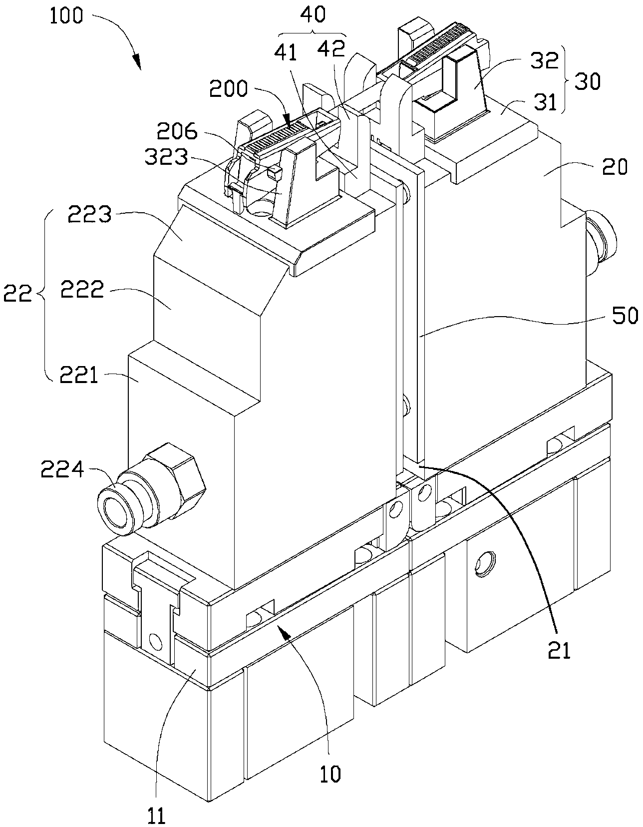
[0016] see figure 1 , the shearing device 100 provided by a preferred embodiment of the present invention is used to position and then cut a plastic product 200 . The plastic product 200 includes a pair of plastic parts 201 and a sprue plug 202 connected between the pair of plastic parts 201 . The sprue tip 202 is formed by solidification of molten plastic left in the mold runner during the injection molding process. After the plastic product 200 is solidified and formed, the sprue tip 202 is waste and must be separated from the pair of plastic parts 201 .

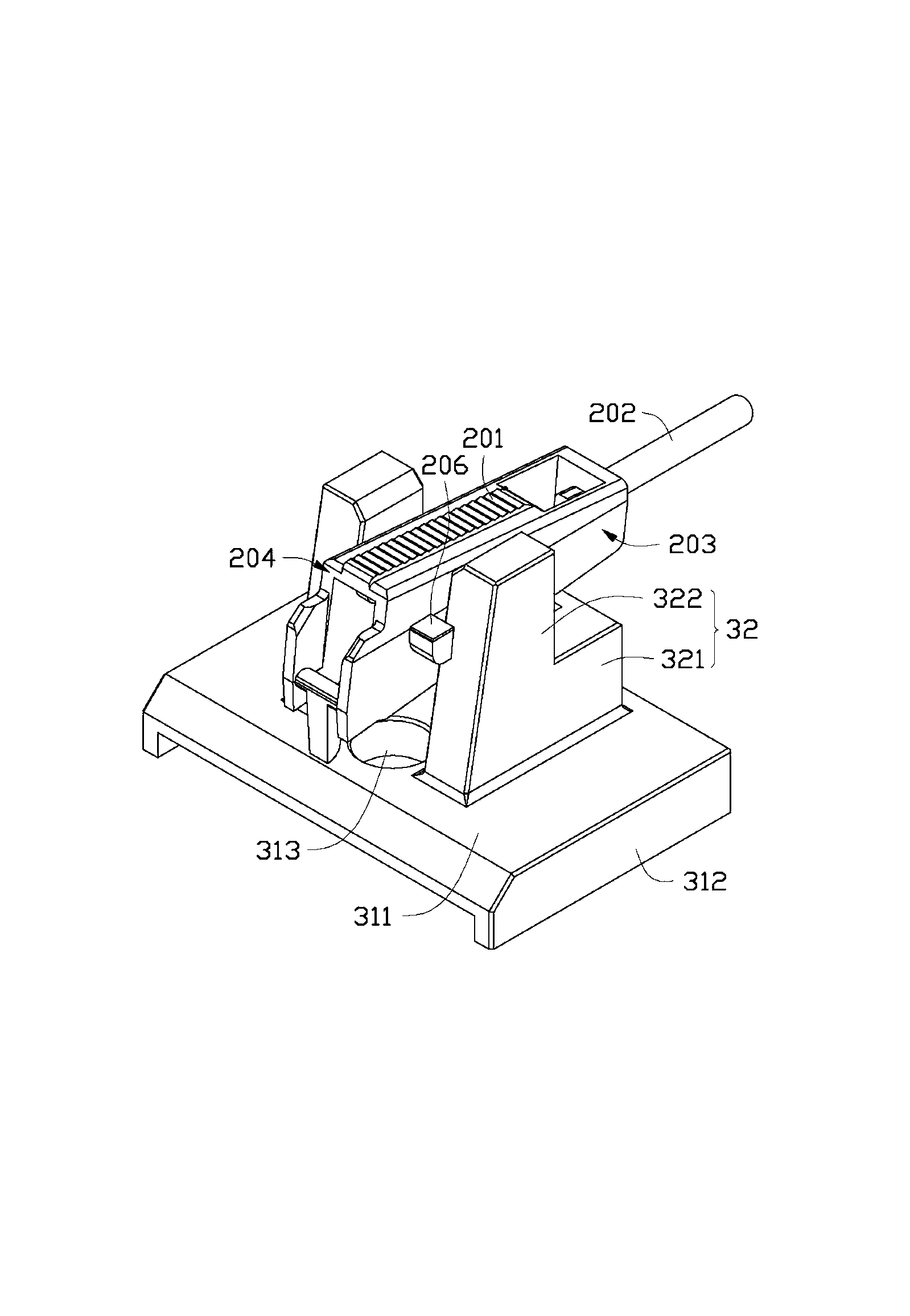
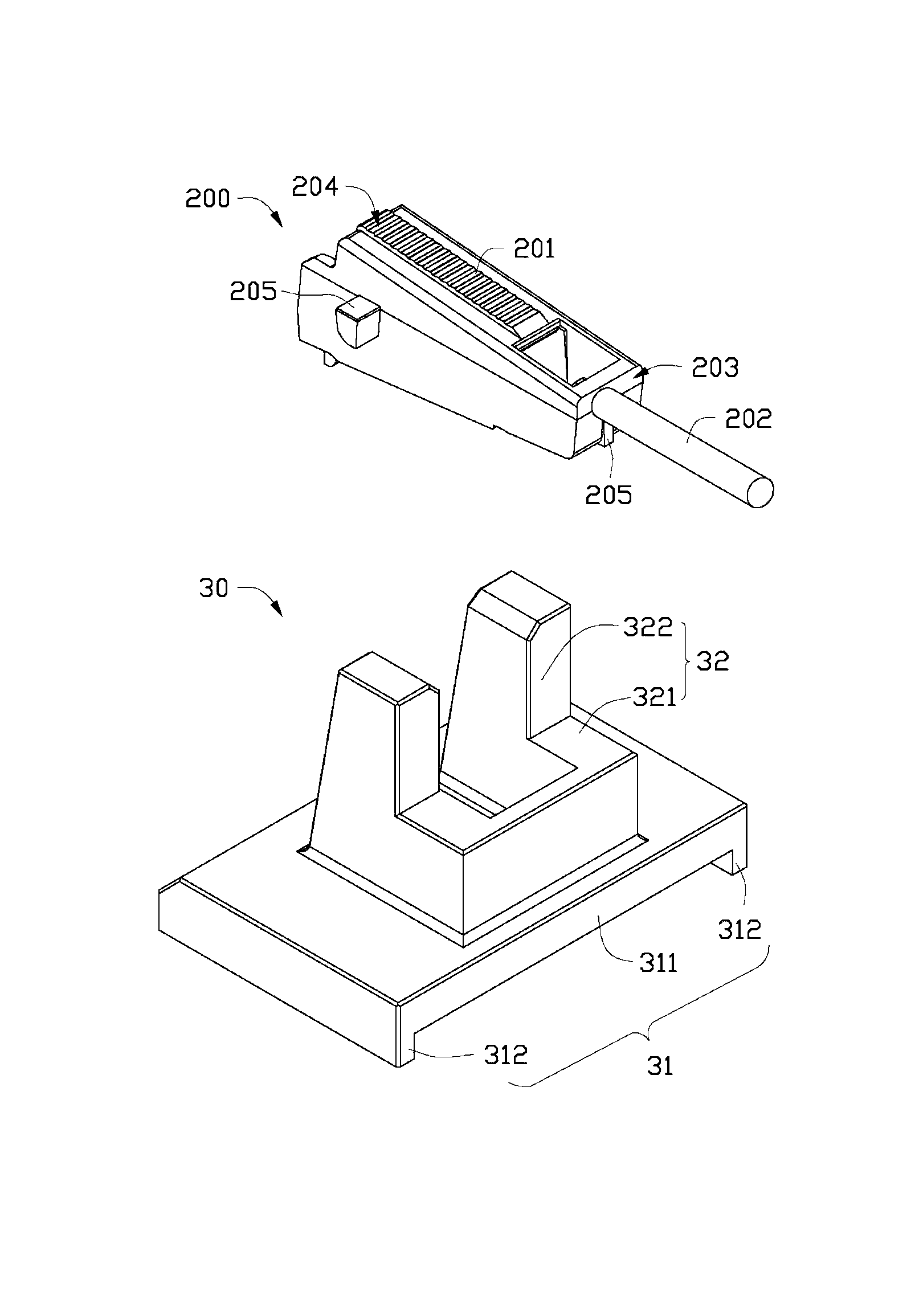
[0017] Please also see figure 2 and image 3 , the shearing device 100 includes an operating portion 10, a base 20 disposed on the operating portion 10, a shearing machine positioning datum 30 disposed on the base 20 and an automatic shear 40, and abutting against the automatic shear 40. and the abutting plate 50 of the base 20 .

[0018] The operating part 10 is composed of several operating components 11 for suppor...


PUM


Abstract

The invention discloses a positioning reference of a shearing machine. The positioning reference of the shearing machine comprises a positioning element arranged horizontally; the positioning element comprises two pushing parts which are opposite and arranged at an interval; each pushing part comprises a reference surface which is an inclined surface forming an included angle with the horizontal plane, wherein the included angle is not zero. Compared with the prior art, the positioning reference of the shearing machine defines the reference surface which is the inclined surface and is matched with a plastic product with a protrusion part, so that in shearing, the protrusion part of the plastic product indents toward one side close to the tail part of the plastic product, and the protrusion part keeps away from the shearing path of a blade; and the plastic product can be prevented from being damaged by shearing in shearing of the plastic product effectively, and the yield of the plastic product is improved. The invention also relates to a shearing device with the positioning reference of the shearing machine.

Description

technical field [0001] The invention relates to a positioning reference, in particular to a shearing machine positioning reference and a shearing device with the positioning reference. Background technique [0002] During the injection molding process of plastic products, the molten plastic raw materials are transported to each cavity through the mold sprue. After the molten plastic is cooled and solidified, multiple plastic products connected by sprue heads can be produced. Then, it is necessary to Fix the plastic product connected to the sprue head, and then use the shearing device to cut off the sprue head, and separate the plastic product from the sprue to obtain the required plastic product. [0003] However, due to the characteristics of its own structure, some products are provided with protruding parts near the sprue tip. In the process of cutting the sprue head, because the design structure originally designed as a positioning reference generally applicable to most...

Claims


Application Information

Patent Timeline
Patent Type & Authority Applications(China)
IPC IPC(8): B29C45/38
Inventor 姜方李发业谭鹏陈翠王剑
Owner HONG FU JIN PRECISION IND (SHENZHEN) CO LTD
Learn More