Humidification device utilizing heating heat energy

A technology of humidification device and supply device, which is applied in the direction of household heating, air humidification system, ultrasonic humidifier, etc. It can solve the problems of insufficient humidification capacity and low energy consumption, and achieve improved humidification capacity, large power generation, and large temperature difference. Effect

Inactive Publication Date: 2013-05-22
QINGDAO UNIV
View PDF14 Cites 7 Cited by
  • Summary
  • Abstract
  • Description
  • Claims
  • Application Information

AI Technical Summary

Problems solved by technology

[0006] Aiming at the contradiction between heating and drying, existing humidification and extra power consumption, and insufficient humidification capacity by simply using heating heat energy, the purpose of this invention is to provide a heat source and cooling system that directly uses heating hot water and humidification feed water as semiconductor thermoelectric power generation. A device that drives the ultrasonic humidification type and fan humidification type humidifier with low energy consumption through the electric energy generated by it to realize effective humidification

Method used


Image

  • Humidification device utilizing heating heat energy
  • Humidification device utilizing heating heat energy
  • Humidification device utilizing heating heat energy

Examples


Embodiment 1

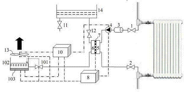
[0024] like figure 1 As shown, a humidification device utilizing heating heat energy is connected to the heating circuit by setting a three-way water inlet in the heating pipeline. The power circulates through the water heater 5 to supply the thermal energy of the hot end surface of the thermoelectric power generation device 7, and is sent back to the heating circuit through the three-way return port through the return valve 2 to realize the heating and hot water circulation; the water storage container 14 is placed at a high position to store water. In the container 14 is humidified feed water, the humidified feed water flows through the water cooler 6 through the water supply valve 12 to cool the cold end face of the thermoelectric power generation device 7, and at the same time its own temperature rises to achieve preheating, and then sent to the humidification container 102 through the pipeline to humidify. The position of the container 102 relative to the water storage co...

Embodiment 2

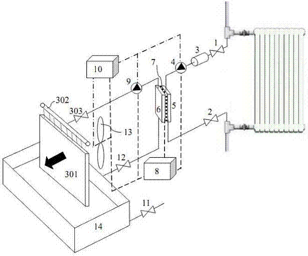
[0028] like image 3 As shown in the figure, a humidifying device using heating heat energy is connected to the heating circuit by setting a three-way water diversion port in the heating pipeline. The heating hot water passes through the water diversion valve 1, filters impurities through the filter 3, and is supplied by the heating hot water circulation pump 4 The power circulates through the water heater 5 to supply the heat energy on the hot end surface of the thermoelectric power generation device 7, and sends it back to the heating circuit through the water return valve 2 through the three-way water return port to realize the circulation of hot water for heating; the water storage container 14 is humidification feed water, humidification The feed water flows through the water supply valve 12 and flows through the water cooler 6 to cool the cold end surface of the thermoelectric power generation device. At the same time, its own temperature rises to realize preheating, and ...


PUM


Abstract

The invention relates to a humidification device utilizing heating heat energy. The humidification device utilizing the heating heat energy comprises a heat source, a cold source, a temperature-difference power generation unit and a humidification unit. The technical scheme is that heating hot water and humidification water supply are adopted as the heat source and the cold source of semiconductor temperature-difference power generation. Electric energy generated by the semiconductor temperature-difference power generation directly drives ultrasonic-humidification-type humidifiers and draught-fan-humidification-type humidifiers to realize effective humidification, wherein the ultrasonic-humidification-type humidifiers and the draught-fan-humidification-type humidifiers are low in energy consumption. The humidification device does not need external energy, is high in heat energy utilization efficiency and strong in humidification ability, applicable to hot-water heating systems with different pressure and forms, can solve problems of heating, drying, prior conflicts between humidification and additional power consumption and insufficient humidification ability when the heating heat energy is simply used, and can be used for air adjustment and control in areas such as residential heating, industry and greenhouses.

Description

technical field [0001] The patent of the present invention relates to a humidifying device utilizing heating heat energy, especially a humidifying device utilizing heating heat energy to drive semiconductor thermoelectric power generation as power, which belongs to the field of air conditioning of energy saving and environmental protection. Background technique [0002] Humidity is an important parameter of the air environment. The heating period in winter is the driest season of the year. The indoor air is drier and the comfort is reduced, which affects the health of the body. In severe cases, it can lead to respiratory diseases. In addition, the static electricity caused by drying will bring security risks. In order to increase the air humidity, it is often used to put wet towels on the heating radiator or sprinkle water on the ground, but the effect is very small; a wide variety of humidifier products are sold in the market, which can meet different humidification needs, b...

Claims


Application Information

Patent Timeline
IPC IPC(8): F24F6/12F24F6/04F24F6/00H02N11/00
CPCY02B30/80Y02B30/70
Inventor 郑艺华刘君张纪鹏马永志
Owner QINGDAO UNIV
Why Eureka
Try Eureka