Eureka AIR delivers breakthrough ideas for toughest innovation challenges, trusted by R&D personnel around the world.

Pipeline detection device based on piezomagnetic effect

A technology of pipeline detection and piezomagnetic effect, which is applied in the direction of pipeline systems, material magnetic variables, mechanical equipment, etc., can solve the problems of high cost, personnel technical level and other factors, and cannot solve the problems of sudden damage to equipment, so as to prevent safety Accidents, improved applicability and convenience, and the effect of improving the level of safety detection technology

Active Publication Date: 2015-05-20
包胜 +2
View PDF5 Cites 0 Cited by
  • Summary
  • Abstract
  • Description
  • Claims
  • Application Information

AI Technical Summary

Problems solved by technology

[0004] Although traditional non-destructive testing (NDT) methods (ultrasonic, magnetic particle, penetrant, eddy current and ray, etc.) have been widely used in industrial testing, it has its limitations: (1) It can only find existing defects, and cannot detect and predict The part where the defect will occur cannot solve the sudden damage of the equipment; (2) the object under inspection generally needs to stop working during the inspection; (3) the surface of the object under inspection is pretreated by removing coating and polishing, which is inefficient and costly (4) The accuracy of the test results is affected by factors such as the shape and structure of the workpiece and the technical level of the personnel; (5) The working conditions of the on-site test are poor and the labor intensity is high, so it is difficult to avoid missing tests

Method used


Image

  • Pipeline detection device based on piezomagnetic effect
  • Pipeline detection device based on piezomagnetic effect
  • Pipeline detection device based on piezomagnetic effect

Examples


Embodiment Construction

[0028] The technical solutions of the present invention will be further described below in conjunction with the accompanying drawings and embodiments.

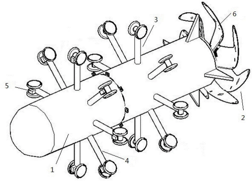
[0029] The embodiment of the present invention provides a pipeline detection device based on the piezomagnetic effect, which includes a body shell 1, a main body running mechanism, a propeller driving mechanism 2, several active link roller mechanisms 3, several driven link roller mechanisms 4 and several signal Collection and processing mechanism 5. Such as figure 1 As shown, the body casing 1 is composed of the fuselage and the tail tightly connected by bolts; the main operating mechanism is placed inside the body casing 1 which is impermeable and airtight; the propeller engine mechanism 2 is fixed at the tail of the body casing 1; The circumference is evenly fixed on the tail of the body shell 1, and the driven link roller mechanism 4 is evenly fixed on the fuselage of the body shell 1 along the circumference; each driven ...


PUM


Abstract

The invention discloses a pipeline detection device based on a piezomagnetic effect. The pipeline detection device based on the piezomagnetic effect comprises a machine body outer shell, a main body running mechanism, a propeller motor mechanism, a plurality of driving connecting rod rolling wheel mechanisms, a plurality of driven connecting rod rolling wheel mechanisms and a plurality of signal acquisition processing mechanisms, wherein the machine body outer shell is formed by the connection of a machine body and a machine tail, and the main body running mechanism is arranged inside the machine body outer shell. The propeller motor mechanism is fixed on the tail portion of the machine body outer shell. The driving connecting rod rolling wheel mechanisms are evenly fixed on the machine tail of the machine body outer shell along the circumference, and the driven connecting rod rolling wheel mechanisms are evenly fixed on the machine body of the machine body outer shell along the circumference. Each driven connecting rod rolling wheel mechanism is connected with a signal acquisition processing mechanism through an internet data center (IDC) interface in a straight-inserting mode. The pipeline detection device based on the piezomagnetic effect can automatically conduct detection and positioning in long distance inside a pipeline where oil conveying work is not stopped. An important means is provided for nondestructive detection inside the pipeline, and the pipeline detection device based on the piezomagnetic effect plays a very important role in guaranteeing the pipeline safety and smooth and long-time running.

Description

technical field [0001] The invention relates to the technical field of oil and gas pipeline detection, in particular to a pipeline detection device based on piezomagnetic effect. Background technique [0002] my country is a country with a large amount of energy, and it is also the country with the second largest energy consumption, and the energy consumption is on the rise. Therefore, under the promotion of such an environment, the oil storage and transportation technology has developed to a certain extent. The main method of oil storage and transportation in my country is pipeline transportation. Over the decades of reform and opening up, oil transportation pipelines have gradually become popular. Among them, oil transportation networks have been established in Northeast, Central South, Central and East China, especially in Northwest China. In addition, regional oil storage and transportation networks have been established in the Sichuan-Chongqing area and the area east of...

Claims


Application Information

Patent Timeline
Patent Type & Authority Patents(China)
IPC IPC(8): G01N27/83F17D5/02
Inventor 包胜林立楼航飞
Owner 包胜
Why Eureka
Eureka Blog
Learn More