Eureka AIR delivers breakthrough ideas for toughest innovation challenges, trusted by R&D personnel around the world.

an automatic air valve

An automatic air valve and air sealing technology, which is applied in the direction of diaphragm valves, valve devices, engine components, etc., can solve complex problems such as failure to achieve automatic locking, and achieve the effect of simple structure

Active Publication Date: 2015-09-23
CIXI VIRTUE
View PDF4 Cites 0 Cited by
  • Summary
  • Abstract
  • Description
  • Claims
  • Application Information

AI Technical Summary

Problems solved by technology

[0002] The sealed air valve is responsible for the suction and discharge of gas. The traditional air valve is composed of valve seat, valve plate, spring, lift limiter, etc. Some air valves do not use springs but use manual rotation devices to lock the valve body , the above two structures are either more complicated, or cannot achieve the function of automatic locking, so it is necessary to design a new structure of sealing air valve

Method used


Image

  • an automatic air valve
  • an automatic air valve

Examples


Embodiment 1

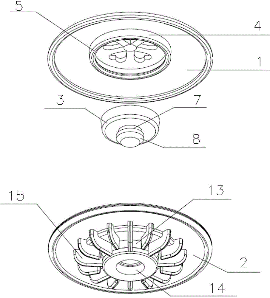
[0018] like Figure 1 to Figure 2 As shown, an automatic air valve includes an upper cover 1, a base 2, an air seal 3, a cylinder 4, an O-shaped seal diameter 5, a plum blossom pattern 6, a neck 7, a washer head 8, and an outer diameter of the air seal. 9. Round tube 10, base convex diameter 11, cylinder inner wall 12, vent hole 13, boss 14, baffle 15, the center of the upper cover 1 is hollowed out, and the bottom of the upper cover 1 is convex around the hollowed out part of the center of the upper cover 1 A cylinder 4 is formed, and there is a circle of O-shaped sealing diameter 5 on the inner wall of the cylinder 4 and along the circumference of the inner wall of the cylinder 4; On the outer wall of the tube 10 and along the circumference of the outer wall of the circular tube 10, there is a circle of base convex diameter 11, the cylinder 4 is in an interference fit with the circular tube 10, and the bottom of the base 2 is a boss 14, which is distributed along the circumf...


PUM


Abstract

The invention relates to an automatic air valve. The automatic air valve comprises an upper cover (1), a base plate (2) and an air sealing cushion (3). The center of the surface of the upper cover (1) is hollow. A cylinder (4) protrudes from the hollow portion around the upper cover (1) below the upper cover (1). An O-shaped sealing diameter (5) is arranged in the periphery direction along the inner wall of the cylinder (4) and on the inner wall of the cylinder (4). A through hole is arranged in the base plate (2). A protruding round pipe (10) is arranged around the upper portion of the base plate (2). A circle base plate protruding diameter (11) is arranged in the periphery direction along the outer wall of the cylinder (10). The cylinder (4) is in interference fit with the round pipe (10). A protruding platform (14) is arranged below the base plate (2). A circle baffle (15) is distributed in the periphery direction along the outer edge of the protruding platform (14). The air sealing cushion (3) is installed in an inner cavity formed by the cylinder (4) and the round pipe (10). The automatic air valve is simple in structure and capable of using air pressure to achieve the automatic sealing.

Description

technical field [0001] The invention belongs to the technical field of seals, in particular to an automatic air valve. Background technique [0002] The airtight air valve is responsible for the inhalation and discharge of the gas. The traditional air valve is composed of a valve seat, a valve plate, a spring, a lift limiter, etc., and some air valves do not use a spring and use a manual rotating device to lock the valve body. , the above two structures are either more complicated or cannot achieve the function of automatic locking, so it is necessary to design a sealing gas valve with a new structure. SUMMARY OF THE INVENTION [0003] The technical problem to be solved by the present invention is to provide an automatic air valve, which can simplify the structure, reduce the production cost, and realize automatic sealing at the same time. [0004] The technical scheme adopted by the present invention to solve the technical problem is: to provide an automatic air valve, w...

Claims


Application Information

Patent Timeline
Patent Type & Authority Patents(China)
IPC IPC(8): F16K7/12
Inventor 叶常青
Owner CIXI VIRTUE
Why Eureka
Eureka Blog
Learn More