Camshaft decompressor

A decompression device and camshaft technology, applied in the direction of valve devices, engine components, machines/engines, etc., can solve the problems of reverse operation of the operating handle, injury to the operator, and difficulty in operating the diesel engine, so as to achieve simple operation and save manpower Effect

Inactive Publication Date: 2013-05-22
CIXI LIANFA MACHINERY
View PDF5 Cites 2 Cited by
  • Summary
  • Abstract
  • Description
  • Claims
  • Application Information

AI Technical Summary

Problems solved by technology

However, for unskilled operators, it is difficult to start the diesel engine smoothly, and it may even cause an accident where the operating handle reverses and injures the operator.

Method used


Image

  • Camshaft decompressor
  • Camshaft decompressor
  • Camshaft decompressor

Examples


Embodiment Construction

[0014] The present invention will be further described in detail below in conjunction with the accompanying drawings and embodiments.

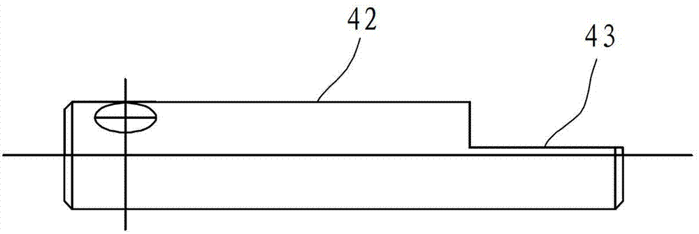
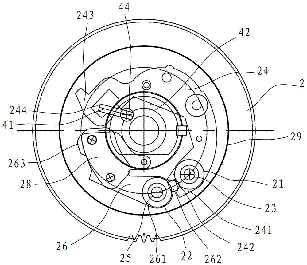
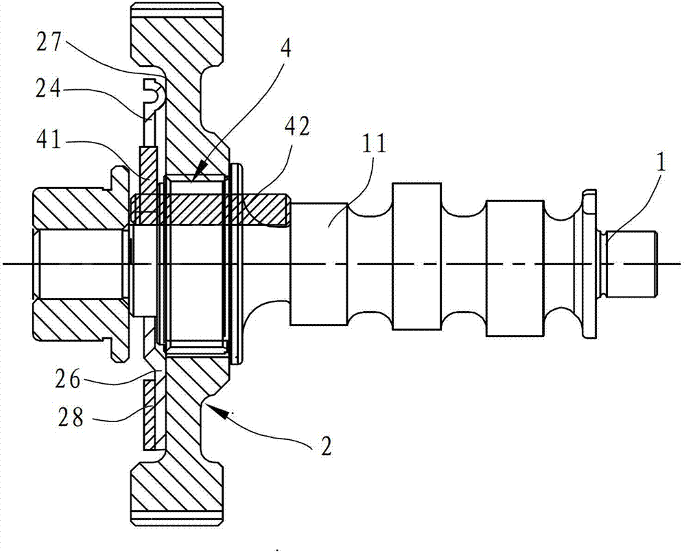
[0015] see figure 1 and figure 2 , a camshaft decompression device, including a camshaft 1, a timing gear 2 sleeved on the camshaft 1, and a bush 3 fixed to the end of the camshaft 1, the bush 3 is located outside the timing gear 2.

[0016] The timing gear 2 is provided with two positioning holes, namely a first positioning hole 21 and a second positioning hole 22 . The first positioning hole 21 is provided with a first flying weight pin 23, through which the first flying weight pin 23 is hinged with the first flying weight 24, and the second positioning hole 22 is provided with a second flying weight pin 25, through which the second flying weight The pin 25 is hinged with a second flying mass 26 . The outer side of the timing gear 2 has a concave surface 27 , and the first flying weight 24 and the second flying weight 26 are both located...


PUM


Abstract

The invention discloses a camshaft decompressor. The camshaft decompressor comprises a camshaft provided with an exhaust cam, a timing gear sleeved on the camshaft and a decompression shaft hinged on the camshaft and adjacent to the exhaust cam. The decompression shaft exceeds a base circle of the exhaust cam to enable a valve to be opened, one side face of the timing gear is provided with a concave surface, a first flyweight and a second flyweight which are bent and positioned in two semicircles of the concave surface respectively are hinged in the concave surface, the first flyweight is provided with a first free end and a second free end which are opposite in rotational direction, the second flyweight is provided with a third free end and a fourth free end which are opposite in rotational direction, the first free end and the third free end are in linkage, a notch facing the circle center of the timing gear is arranged at the second free end, the decompression shaft comprises a stirring portion and a decompression support portion which are mutually angled, the stirring portion extends into the notch, and the decompression support portion extends axially along the camshaft. By the aid of the flyweights driven under the action of centrifugal force, the decompression shaft is stirred to leave or be positioned below a tappet so as to achieve automatic decompression during starting of a diesel engine, so that operation is simple, and labor is saved.

Description

technical field [0001] The invention relates to a camshaft for gas distribution of a diesel engine, in particular to an automatic decompression device for the camshaft. Background technique [0002] When the diesel engine intakes impulse, the air is first sucked into the cylinder and compressed rapidly. When the pressure rises to 300~400KPa and the temperature rises to 500~600℃, diesel is injected into the cylinder at the end of the compression process. The diesel injected into the cylinder mixes with air to form a combustible mixture, which burns in the combustion chamber to do work. In order to improve the performance of the diesel engine, sufficient air intake must be ensured, and the air utilization rate should be improved as much as possible. However, when the diesel engine is started, it needs to inhale new air for compression. Near the end of compression, there will be a large compression resistance in the cylinder. If the decompression is not performed at this time,...

Claims


Application Information

Patent Timeline
IPC IPC(8): F01L13/08
Inventor 史伯棉史剑侠
Owner CIXI LIANFA MACHINERY
Why Eureka
Try Eureka