Pressure reduction mechanism for air distribution cam shaft of diesel engine

A technology of decompression mechanism and camshaft, which is applied to machines/engines, mechanical equipment, engine components, etc., can solve the problems of insufficient intake air, difficulty in starting the diesel engine, affecting the air compression effect, etc., and achieves elimination of exhaust valve clearance, The effect of reducing drag

Active Publication Date: 2013-10-09
LONCIN MOTOR
View PDF1 Cites 0 Cited by
  • Summary
  • Abstract
  • Description
  • Claims
  • Application Information

AI Technical Summary

Problems solved by technology

However, since the diesel engine must ensure sufficient air intake to effectively perform work, if the pressure is released all the time before reaching high speed, it will cause insufficient intake air, affect the air compression effect, and make it difficult to start the diesel engine.

Method used


Image

  • Pressure reduction mechanism for air distribution cam shaft of diesel engine
  • Pressure reduction mechanism for air distribution cam shaft of diesel engine
  • Pressure reduction mechanism for air distribution cam shaft of diesel engine

Examples


Embodiment Construction

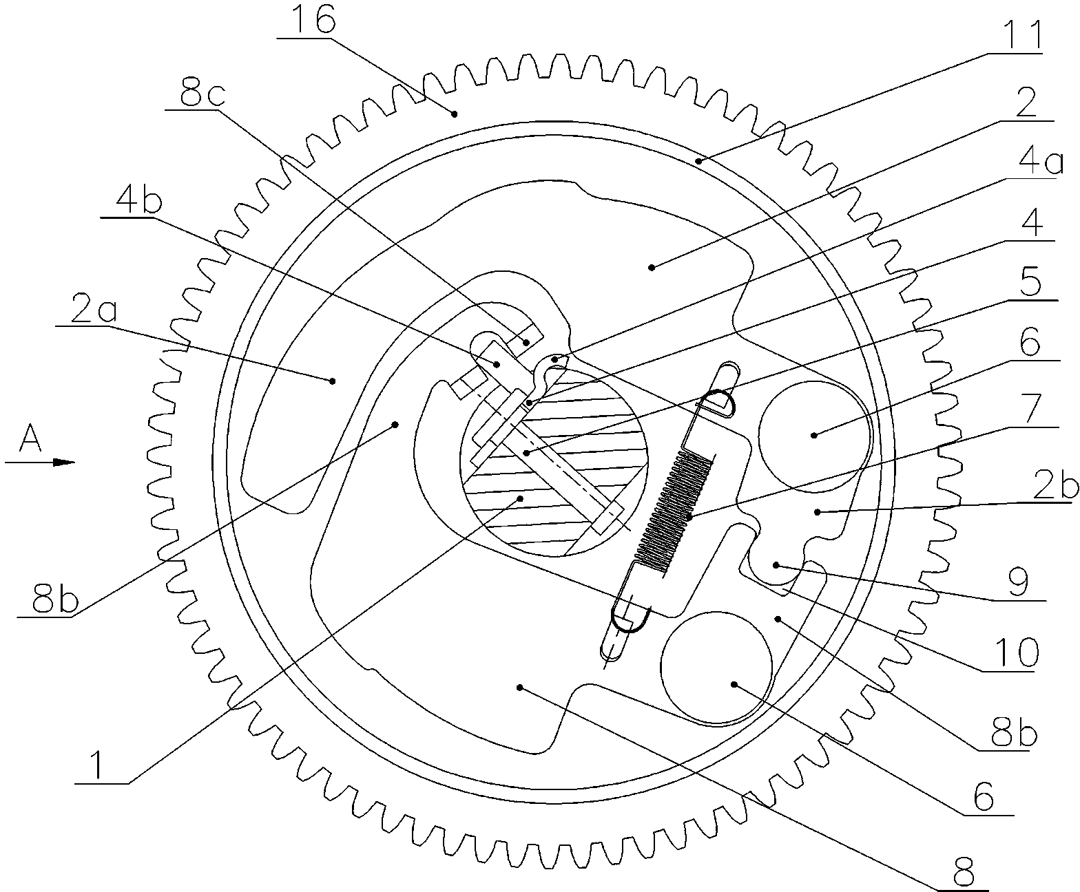
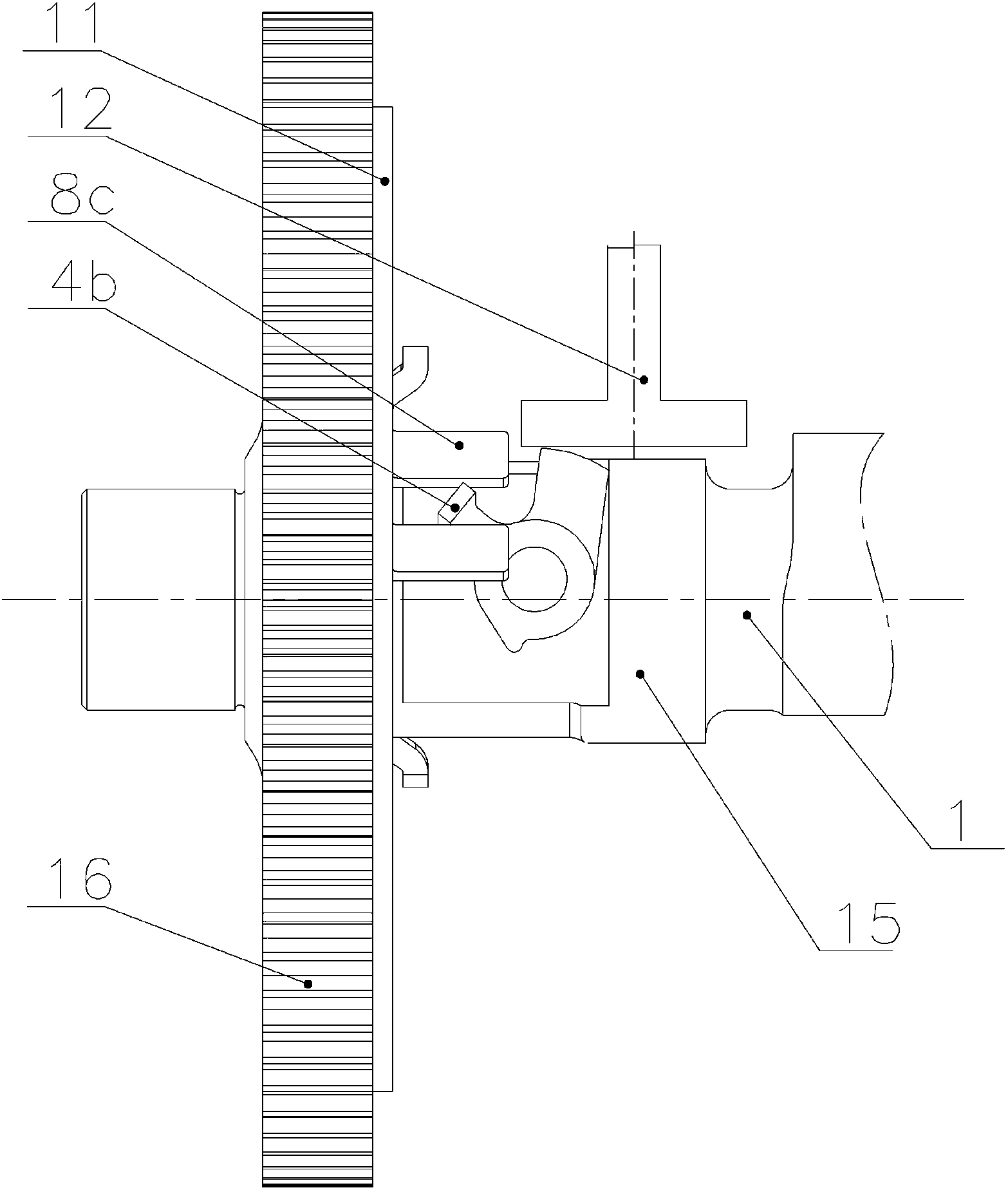
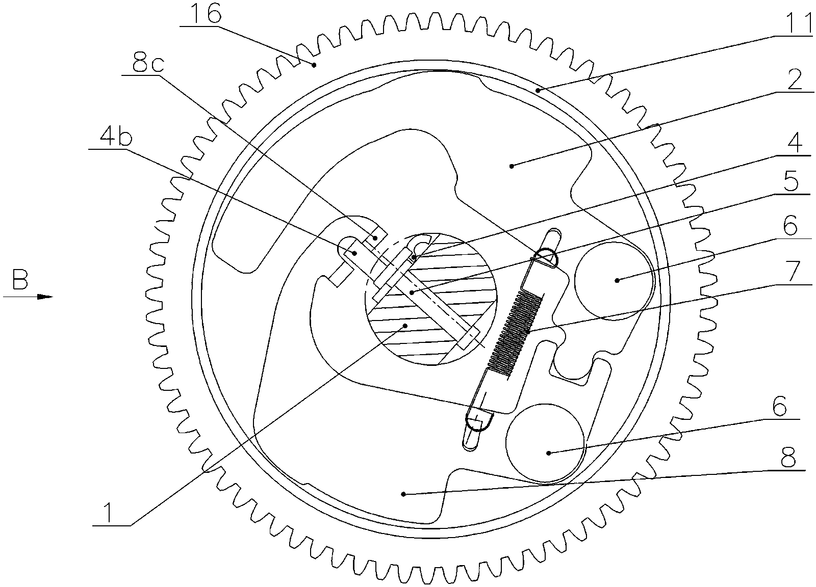
[0024] see Figure 1 to Figure 4, the decompression mechanism of the gas distribution camshaft of the diesel engine. The gas distribution camshaft 1 of the diesel engine is provided with intake and exhaust cams, and a timing gear 16 is fixed on the camshaft 1. The pressure block 4 and the decompression block 4 are located beside the exhaust cam 15 . The decompression block 4 includes a decompression support portion 4a and a lever portion 4b. An acute-angled angle is formed between the decompression support portion 4a and the lever portion 4b of the decompression block 4, and the angle of the acute-angled angle is 60°. ~80°, preferably 65°. The corner between the decompression support part 4a and the lever part 4b of the decompression block 4 is hinged with the camshaft 1 through a pivot pin 5, and the camshaft 1 is provided with a tangent plane on the shaft section of the decompression block 4, and the exhaust cam The axial end adjacent to the base circle portion of 15 and t...


PUM


Abstract

The invention discloses a pressure reduction mechanism for an air distribution cam shaft of a diesel engine. A shifting centrifugal block and a balance weight centrifugal block are arranged on the adjacent axial end faces of a timing gear and an air exhaust cam of the cam shaft respectively; hinging pivots of the shifting centrifugal block and the balance weight centrifugal block deviate from the circle center of the timing gear respectively; each of the shifting centrifugal block and the balance weight centrifugal block is provided with a first free end and a second free end; each hinging pivot is positioned between the two free ends; the second free end of the balance weight centrifugal block and the second free end of the shifting centrifugal block are oppositely clamped to form linkage; the first free end of the shifting centrifugal block is clamped with a shifting rod part of a pressure reduction block; and a resetting tension spring is positioned between the first free ends of the balance weight centrifugal block and the shifting centrifugal block and is used for connecting the balance weight centrifugal block and the shifting centrifugal block at positions close to the hinging pivots. The pressure reduction mechanism can reduce the pressure of compressed air in a cylinder when the diesel engine is started, so that the resistance is reduced; and furthermore, the pressure reduction block stops reducing the pressure when the timing gear rotates at a low speed, so that work can be done in an enough air inlet amount.

Description

technical field [0001] The invention relates to a gas distribution camshaft of a diesel engine, in particular to a decompression mechanism for a gas distribution camshaft of a diesel engine. Background technique [0002] Compared with gasoline used in gasoline engines, the diesel used in diesel engines has poor evaporation. Therefore, it is impossible for diesel to form a mixture with air outside the cylinder like gasoline before entering the engine cylinder to burn and explode to do work. When the diesel engine is in the intake impulse, the air is first sucked into the cylinder and compressed rapidly. When the pressure rises to 300-400KPa and the temperature rises to 500-600°C, diesel is injected into the cylinder at the end of the compression process. The diesel injected into the cylinder mixes with air to form a combustible mixture, which burns in the combustion chamber to do work. In order to improve the performance of the diesel engine, sufficient air intake must be en...

Claims


Application Information

Patent Timeline
Patent Type & Authority Patents(China)
IPC IPC(8): F01L13/08
Inventor 景华阳刘荣利洪方平付强曾令波刘祥江
Owner LONCIN MOTOR
Why Eureka
Try Eureka