
Die and method for braiding curve limiting mesh of inflatable membrane

A technology of inflatable film and limiting net, which is applied in the direction of braided fabrics, hand-woven, textiles and papermaking, etc., and can solve problems such as inability to make arc-shaped and curved surface limiting nets

Active Publication Date: 2013-05-22
HARBIN INST OF TECH
View PDF6 Cites 2 Cited by
  • Summary
  • Abstract
  • Description
  • Claims
  • Application Information

AI Technical Summary

Problems solved by technology

[0003] The present invention solves the problem that the prior art cannot make arc-shaped surface limiting nets

Method used


Image

  • Die and method for braiding curve limiting mesh of inflatable membrane
  • Die and method for braiding curve limiting mesh of inflatable membrane
  • Die and method for braiding curve limiting mesh of inflatable membrane

Examples


specific Embodiment approach 1

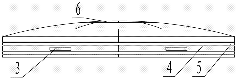
[0008] Specific implementation mode one: combine figure 1 and figure 2 Describe this embodiment, a mold for weaving an inflatable film curved surface limiting net described in this embodiment, the mold includes a template 1, the template 1 is in the shape of a round cake, the lower end surface of the template 1 is a plane, and the upper surface of the template 1 The end face is an arc-shaped curved surface and the center position of the upper end face of the template 1 is the highest point of the arc-shaped curved surface.

specific Embodiment approach 2

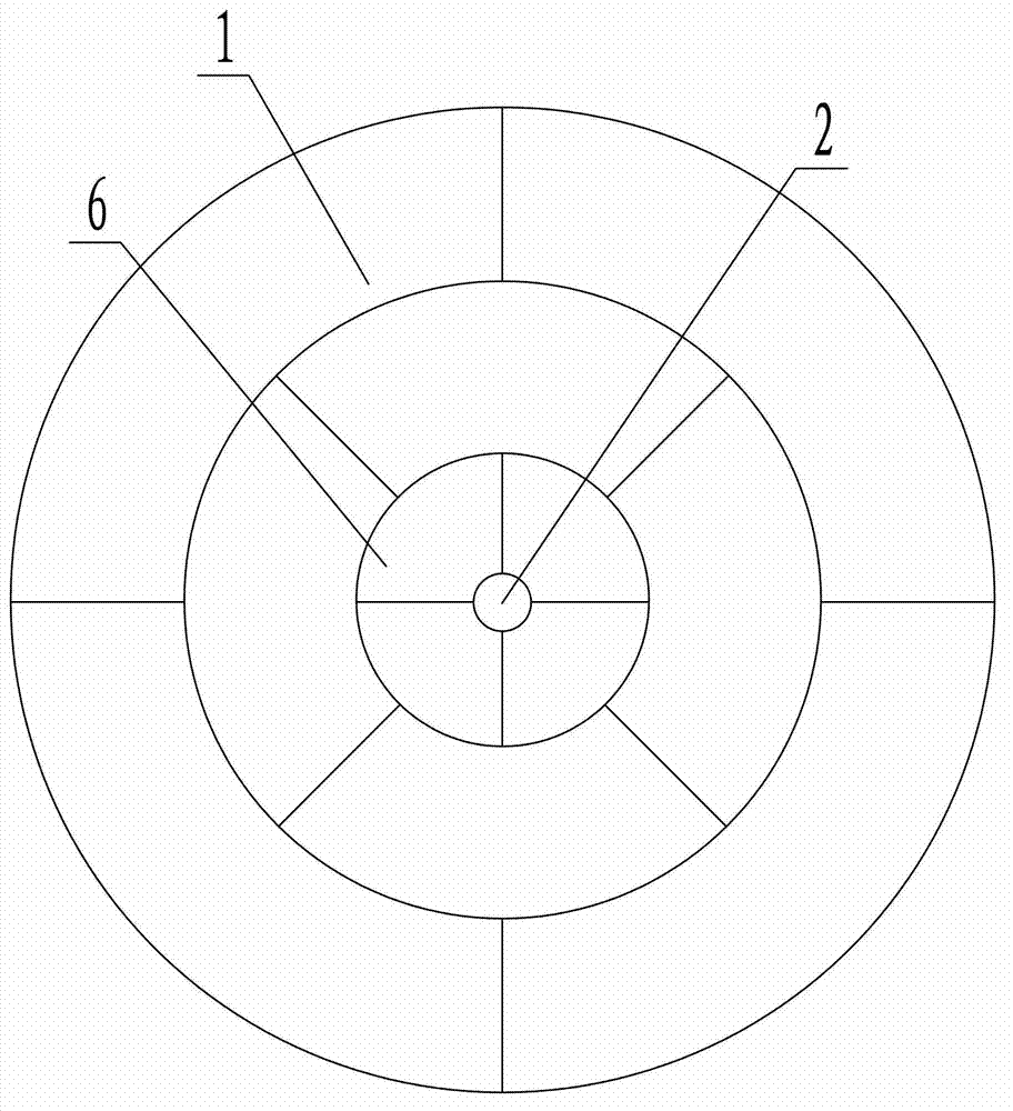
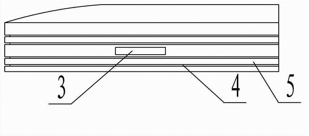
[0009] Specific implementation mode two: combination figure 1 , figure 2 , image 3 , Figure 4 and Figure 5 Describe this embodiment, the formwork 1 described in this embodiment is composed of a central formwork 6 and a plurality of annular formworks, the central formwork 6 is cylindrical, and the plurality of annular formworks are connected in the center from the inside to the outside according to the order of the outer diameter from small to large. On the formwork 6, each annular formwork is composed of multiple arc-shaped plates, and the joints of the multiple arc-shaped formworks in each annular formwork are staggered in the ring direction from the joints of the multiple arc-shaped formworks in the adjacent annular formwork , set in this way, the template 1 is divided into multiple pieces, which facilitates the disassembly and assembly of the template 1, and the other components and connections are the same as those in the first embodiment.

specific Embodiment approach 3

[0010] Specific implementation mode three: combination figure 2 Describe this embodiment, the mold described in this embodiment also includes a central column 2, the middle position of the upper end surface of the template 1 is provided with a column hole, the central column 2 passes in the column hole of the template 1, the upper end surface of the central column 2 and the template 1's upper surface coincides with each other, so that it is convenient to make concentric circles on the upper end surface of template 1 with the center point of the upper end surface of template 1 as the center, so that it is more convenient for the mold to weave the limit net. Other components and connection relations are the same as The second embodiment is the same.


PUM


Abstract

The invention discloses a die and a method for braiding a curve limiting mesh of an inflatable membrane, belongs to the field of fabrication of the limiting net, and solves the problem that an arc curve limiting mesh cannot be fabricated by the prior art. In order to solve the problem, the die for braiding the curve limiting mesh of the inflatable membrane is provided. The die comprises a template; the template is of a cake shape; the upper end face of the template is an arc curve surface; the center position of the upper end face of the template is the highest point of the arc curve surface; the method for braiding the curve limiting mesh of the inflatable membrane by the die is achieved according to the following steps that: 1, a plurality of annular braided lines are arranged around the center of the upper end face of the template as a circle center at the upper end face of the template; and 2, the plurality of annular braided lines are connected together through a plurality of curve braided lines to form a braided mesh; and the length of each edge of each grid in the braided mesh is smaller than 3cm. The method disclosed by the invention is used for braiding the curve limiting mesh of the inflatable membrane.

Description

technical field [0001] The invention relates to a mold and a method for weaving an inflatable film curved surface limit net, belonging to the field of limit net production. Background technique [0002] In the aerospace field at this stage, some specific equipment often uses inflatable films, and requires that one side of the inflatable film form a regular arc-shaped structure after inflation. In order to achieve this requirement, the required arc shape can be adopted The limit net with curved surface structure is realized on the outside of the inflatable film, but because the limit net must strictly meet the required arc-shaped surface structure, it is difficult to realize the production of this arc-shaped curved surface limit net in the prior art. Contents of the invention [0003] The invention solves the problem that the prior art cannot manufacture the arc-shaped and curved surface limiting net. [0004] In order to solve the above technical problems, a mold for weav...

Claims


Application Information

Patent Timeline
Patent Type & Authority Applications(China)
IPC IPC(8): D04C7/00
Inventor 谭惠丰王长国林国昌卫剑征谢志民苗常青
Owner HARBIN INST OF TECH
Learn More