
Center floating type chuck

A floating, top technology, applied in the direction of chuck, tailstock/top, turning equipment, etc., can solve problems such as clamping workpieces, achieve the effect of reliable cooperation, improved stability, and improved clamping accuracy

Active Publication Date: 2013-05-22
TSINGHUA UNIV
View PDF5 Cites 14 Cited by
  • Summary
  • Abstract
  • Description
  • Claims
  • Application Information

AI Technical Summary

Problems solved by technology

However, existing chucks cannot clamp the workpiece while centering the workpiece with the center process hole

Method used


Image

  • Center floating type chuck
  • Center floating type chuck
  • Center floating type chuck

Examples


Embodiment Construction

[0033]Embodiments of the present invention are described in detail below, examples of which are shown in the drawings, wherein the same or similar reference numerals designate the same or similar elements or elements having the same or similar functions throughout. The embodiments described below by referring to the figures are exemplary only for explaining the present invention and should not be construed as limiting the present invention.

[0034] In describing the present invention, it should be understood that the terms "center", "longitudinal", "transverse", "upper", "lower", "front", "rear", "left", "right", " The orientations or positional relationships indicated by "vertical", "horizontal", "top", "bottom", "inner" and "outer" are based on the orientations or positional relationships shown in the drawings, and are only for the convenience of describing the present invention and Simplified descriptions, rather than indicating or implying that the device or element refer...


PUM


Abstract

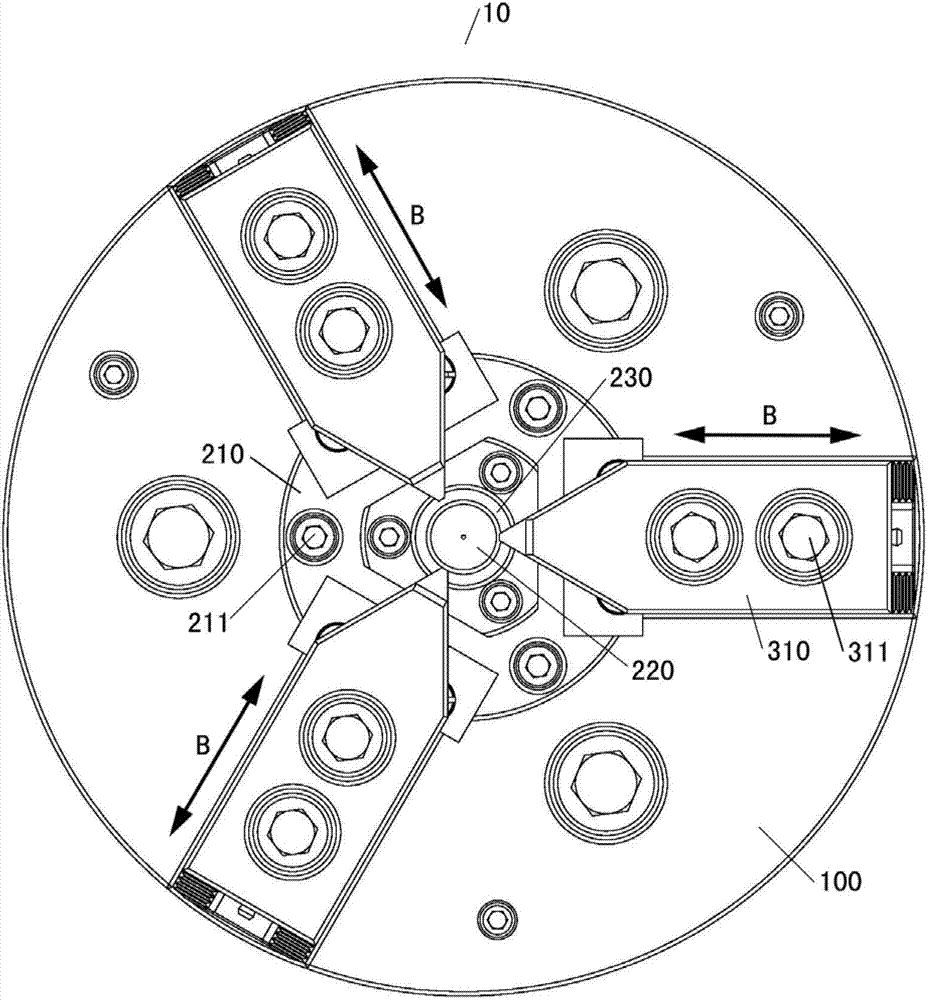
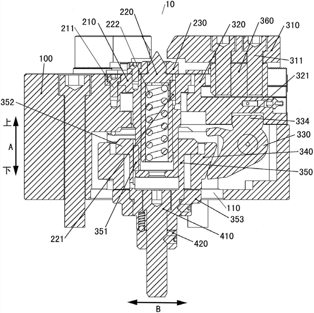
The invention discloses a center floating type chuck. The center floating type chuck comprises a chuck body, a locating unit, a floating clamp unit and a connecting unit. A center hole is formed in the chuck body. The locating unit is matched in the center hole and used for locating centers of workpieces. The floating clamp unit is arranged on the chuck body and comprises a plurality of high jaws capable of carrying out asynchronous movement so as to clamp the workpieces whose centers are located on the locating unit. The connecting unit is respectively connected with the floating clamp unit and a drive device which is used for driving the floating clamp unit. The center floating type chuck has the advantages of clamping the workpieces, reducing locating errors of multiple clamps and the like under the condition of being capable of locating the workpiece centers.

Description

technical field [0001] The invention relates to the field of mechanical manufacturing, in particular to a tip floating chuck. Background technique [0002] With the development of modern manufacturing technology, higher requirements are put forward for the accuracy of machine tools and their main functional parts. The clamping accuracy of the chuck is a major factor affecting the machining error of the workpiece. The hydraulic power chuck is a general-purpose fixture on a CNC machine tool that uses a high-speed rotary cylinder as the power source. Its accuracy directly affects the overall accuracy of the CNC machine tool, and it is one of the key functional components of the CNC machine tool. [0003] For some workpieces with high precision requirements and many processing procedures, it is necessary to process a central process hole on the workpiece for auxiliary positioning, so as to reduce the positioning error caused by multiple clamping. However, the existing chuck can...

Claims


Application Information

Patent Timeline
Patent Type & Authority Applications(China)
IPC IPC(8): B23B31/175B23B23/00
Inventor 张建富冯平法王健健郁鼎文吴志军
Owner TSINGHUA UNIV
Learn More