
Novel optical probe

An optical probe, a new type of technology, is applied in medical science, sensors, diagnostic recording/measurement, etc. It can solve the problems of difficulty in scanning system stability, scrapping of probes, complex probe structure, etc., and achieve a good foundation for technology transformation and extended use The effect of long life and broad market prospects

Active Publication Date: 2013-05-22
TIANJIN UNIV
View PDF8 Cites 13 Cited by
  • Summary
  • Abstract
  • Description
  • Claims
  • Application Information

AI Technical Summary

Problems solved by technology

The disadvantages of this probe are: first, the instability in the working process; second, due to the limited service life of the hose, the probe will be scrapped in advance
[0006] The Chinese patent publication number is CN102697455A, and the patent literature named "OCT Electronic Gastroscopy System" reports a technical solution for placing the driver inside the probe. The driver is directly connected to the reflective prism. The disadvantage of this structure is that it is difficult to install. Moreover, the driver is directly connected to the prism. During the dynamic scanning process, the reflected optical signal of the prism will be unstable, resulting in the reflected optical signal not being able to enter the transmission fiber.
Moreover, the use of this driver will generate noise, which will affect the collection of useful information and is not conducive to detection
[0007] The Chinese patent publication number is CN1593351A, and the patent literature titled "Medical Micro-Ultrasound through Endoscope-OCT Probe" discloses an optical probe with a micro-driver installed at the end of the probe. This probe combines an ultrasonic transducer , which expands the detection function to a certain extent, but the biggest problem lies in the stability of the scanning system and the ease of assembly. This kind of probe also directly connects the driver to the prism, and the signal light transmission will be unstable during the scanning process. Sex, and the structure of this probe is more complicated, especially when installing the transducer and the driver, the arrangement of the leads is a troublesome problem

Method used


Image

  • Novel optical probe
  • Novel optical probe

Examples


Embodiment Construction

[0016] The present invention will be further described in detail below in combination with specific embodiments.

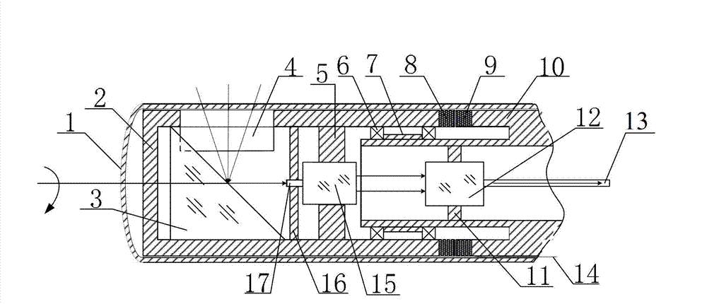
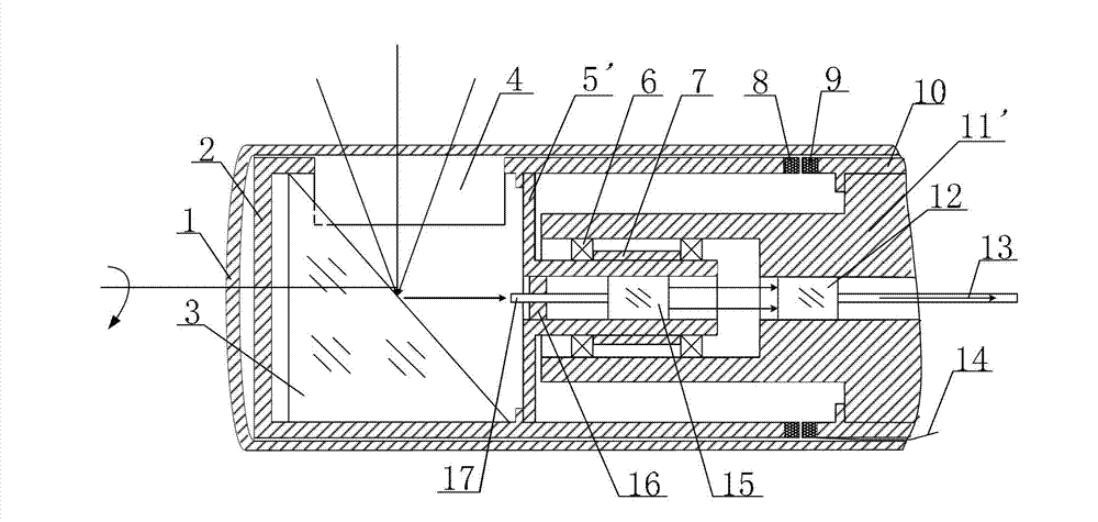
[0017] Such as figure 1 As shown, a technical solution of the novel optical probe of the present invention is to include an annular ultrasonic motor and a rotating assembly and a stationary assembly arranged in a transparent protective sheath 1; the annular ultrasonic motor is driven by an annular ultrasonic drive rotor 8 and an annular ultrasonic drive Stator 9; the rotating assembly includes a rotating sleeve 2, the rotating sleeve 2 is fixedly connected with the annular ultrasonic drive rotor 8, the wall of the rotating sleeve 2 is provided with a light hole 4, the A reflective prism 3 for reflecting optical signals and a first self-focusing lens 15 are fixed inside the rotating sleeve 2, and the first self-focusing lens 15 is fixed to the rotating sleeve 2 through a fixed bracket 5; the stationary assembly includes a stationary sleeve 10. The stationary sleev...


PUM


Abstract

The invention discloses a novel optical probe which comprises a rotary assembly and a static assembly, wherein the rotary assembly and the static assembly are combined with each other through a rotary connector. The rotary assembly mainly comprises a reflecting prism used for reflecting light signals, a ringlike ultrasonic motor rotor, a light unthreaded hole and a self-focusing lens. The static assembly mainly comprises a ringlike ultrasonic motor stator, a self-focusing lens and a bearing. The ringlike ultrasonic motor stator and the motor are respectively fixed on a static sleeve and a rotary sleeve in an integrated mode. The friction force is generated after the ringlike ultrasonic motor is electrified, so that the whole rotary sleeve can conduct 360 degrees rotary screening. The screened light signals enter into the first self-focusing lens to exit parallel light through the reflective prism, and then the exited light enters into the second self-focusing lens to output screening information through transmission optical fibers. The novel optical probe is simple in operation, can not be interfered by electromagnetism in the process of working and can achieve the 360 degrees rotary screening. In addition, the novel optical probe is promising in market prospect, is good in technical transformation foundation and has wide social benefits at the same time.

Description

technical field [0001] The invention relates to a medical and optical detection instrument, in particular to an optical signal transceiving system with a rotatable scanning function. Background technique [0002] With the continuous development of photoelectric detection technology, various advanced detection technologies are applied in industrial and medical fields. OCT (Optical Coherence Tomography, Optical Coherence Tomography) is one of the detection technologies. It uses the basic principle of weak coherent light interferometer to detect the back reflection or several scattering signals of incident weak coherent light at different depths of biological tissue. , through scanning, two-dimensional or three-dimensional structural images of biological tissues can be obtained. At present, this technology is mainly used in the medical field. This technology puts forward strict requirements on the probe when performing biomedical testing. The probe should be as small as possib...

Claims


Application Information

Patent Timeline
IPC IPC(8): A61B5/00
Inventor 贾大功张玉龙张红霞刘铁根张以谟
Owner TIANJIN UNIV
Learn More