
Time-based detection method for shaded parts of photovoltaic panels

A photovoltaic cell panel and detection method technology, which is applied in image analysis, instrumentation, calculation, etc., can solve the problems of not being able to truly reflect the shaded part of photovoltaic cells, increasing the use cost of photovoltaic power generation systems, etc., to improve accuracy and speed, Simple calculation and fast convergence

Inactive Publication Date: 2016-02-03
CHONGQING UNIV
View PDF3 Cites 0 Cited by
  • Summary
  • Abstract
  • Description
  • Claims
  • Application Information

AI Technical Summary

Problems solved by technology

The current maximum power point tracking method is to make the photovoltaic cell array always work near the maximum power point by assuming a shadow area, so as to improve the power generation efficiency. Therefore, the traditional maximum power point tracking method assumes that the shadow area cannot truly reflect the photovoltaic shaded part of the battery
[0003] In addition, in the traditional maximum power point tracking method, it is also necessary to collect the shading degree of all photovoltaic cells in the photovoltaic panel, which requires a large number of light intensity sensors to collect multiple signals, which undoubtedly increases the cost of photovoltaic power generation systems.

Method used


Image

  • Time-based detection method for shaded parts of photovoltaic panels
  • Time-based detection method for shaded parts of photovoltaic panels
  • Time-based detection method for shaded parts of photovoltaic panels

Examples


Embodiment Construction

[0046] Embodiments of the present invention are described in detail below, examples of which are shown in the drawings, wherein the same or similar reference numerals designate the same or similar elements or elements having the same or similar functions throughout. The embodiments described below by referring to the figures are exemplary only for explaining the present invention and should not be construed as limiting the present invention.

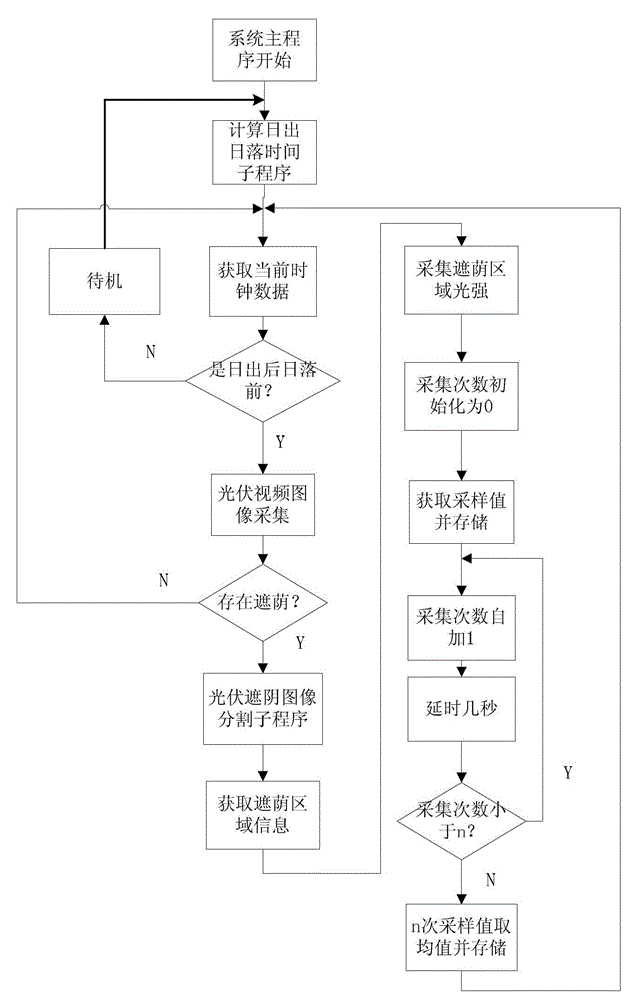
[0047] Such as figure 1 As shown, the detection method of the shading part of the photovoltaic panel based on the time period includes the following steps: Step 1, judge whether the current time is in the time period after sunrise and before sunset: if it is within the time period, then collect the photovoltaic panel the actual image A, otherwise end the operation. The present invention only collects the actual image of the photovoltaic battery panel in the time period after sunrise and before sunset, thereby reducing energy consumption...


PUM


Abstract

The invention provides a detection method of a photovoltaic cell panel shading portion based on a time interval and belongs to the field of photovoltaic power generation. The detection method of the photovoltaic cell panel shading portion based on the time interval includes the following steps: S1, judging whether the current time is in a time quantum from sunrise to sunset, collecting a practical image A of the photovoltaic cell panel when the current time is in the time quantum from sunrise to sunset, otherwise finishing the operation; S2, comparing the practical image A which is conducted grey processing with an original image B, wherein the original image B refers to a grayscale image without a shadow portion, finishing the operation when the practical image A which is conducted grey processing is identical with the original image B, and conducting image cutting on the shadow portion of the practical image A when the practical image A which is conducted grey processing is different from the original image B, and obtaining a shading area of the photovoltaic cell panel. The detection method of the photovoltaic cell panel shading portion based on the time interval collects the practical image of the photovoltaic cell panel only in the time quantum from sunrise to sunset, reduces detection energy consumption, conducts image cutting by combining a K-means clustering method and a firmware control memory (FCM) method based on one-dimensional histogram and improves precision and speed of image cutting.

Description

technical field [0001] The present invention relates to a photovoltaic power generation system, in particular to a detection method for the shading part of a photovoltaic battery panel based on a time period. Background technique [0002] In the popularization process of photovoltaic power generation system, the key lies in how to improve the utilization rate of solar energy. Photovoltaic power generation systems will inevitably be blocked by shadows such as trees, tall buildings, clouds, and birds during the working process. safe question. In partial shading conditions, the maximum power point tracking method is an effective method to increase the output power of photovoltaic panels. The current maximum power point tracking method is to make the photovoltaic cell array always work near the maximum power point by assuming a shadow area, so as to improve the power generation efficiency. Therefore, the traditional maximum power point tracking method assumes that the shadow a...

Claims


Application Information

Patent Timeline
Patent Type & Authority Patents(China)
IPC IPC(8): G06T7/00
Inventor 段其昌段盼隆霞杨帆胡博
Owner CHONGQING UNIV
Learn More